What is the maximum size of a heat sink?
- Yongxing
- 14 May ,2026
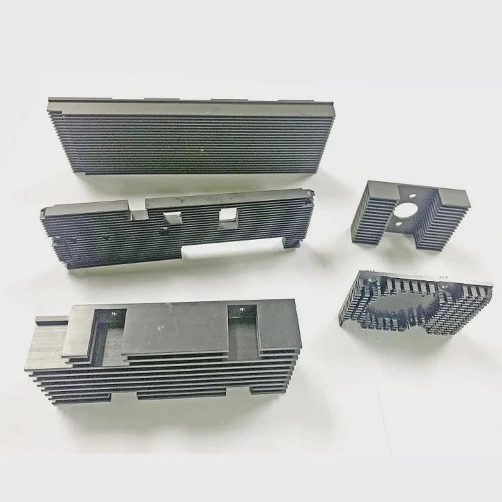
Heat sinks are vital for keeping electronics cool. Many engineers wonder if making them bigger always helps solve overheating problems.
The maximum size of a heat sink depends on multiple factors including airflow, space constraints, thermal resistance, and system design. Bigger is not always better.
Choosing the right heat sink size needs understanding of both the device and the environment it operates in. Oversizing or undersizing can both cause issues in performance.
How does heat sink size affect thermal performance?
Heat sinks remove heat from devices. Too small, and they fail. Too large, and they may not work efficiently. Finding the right balance is key.
Larger heat sinks generally provide lower thermal resistance and better cooling, but only if airflow and mounting allow full heat transfer.
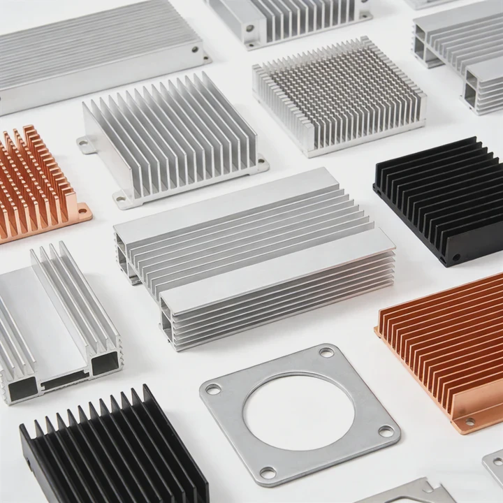
Heat sink size directly impacts thermal performance. Larger surface area means more space for heat to move from the device to the surrounding air. However, the gains are not linear. Doubling size does not double cooling. Airflow plays a major role. A tall or wide heat sink in low airflow conditions may trap heat rather than release it. Design also matters. Fins should allow air to flow freely. Materials like aluminum or copper have high thermal conductivity, but if the heat cannot move to air, size alone does little.
Thermal resistance table
| Heat Sink Type | Size Effect | Airflow Dependency |
|---|---|---|
| Small PCB-mounted | High resistance | Low |
| Medium finned | Moderate | Moderate |
| Large extruded | Low resistance | High |
Even with a perfect material, physical space limits how big a heat sink can be. Too large, and it may not fit in the device or block other components. Weight is another factor. Heavy heat sinks can stress circuit boards. Therefore, engineers must consider size carefully. Using simulation tools helps predict thermal performance before building the final product. These tools model heat transfer and airflow for different sizes.
Key points
- Thermal performance improves with size, but only with adequate airflow.
- Surface area and fin design affect efficiency.
- Material conductivity matters but does not replace proper design.
- Practical limits like weight and space can restrict maximum size.
Which design factors limit heat sink dimensions?
Many think heat sinks can be as big as possible. In reality, design constraints often stop growth. Space, weight, airflow, and mounting play major roles.
The maximum dimension of a heat sink is limited by the device size, available airflow, mechanical clearance, and weight considerations.
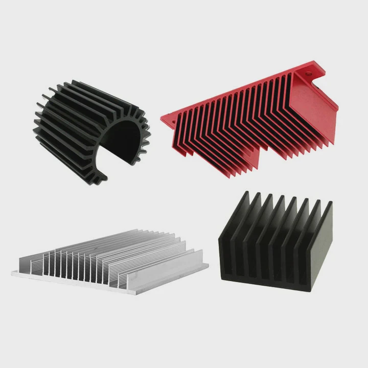
Heat sinks must fit inside their system. Electronics have limited space. Oversized heat sinks may interfere with components or enclosures. Weight is also important. Heavy heat sinks can bend boards or require stronger mounting. Airflow is critical. A big heat sink that blocks air may reduce cooling instead of improving it. Mechanical design factors include screw placement, mounting points, and connector locations. Designers also need to consider aesthetics and transport. Sometimes, external devices like fans or shrouds further limit size.
Design constraints table
| Factor | Limitation |
|---|---|
| Physical space | Cannot exceed device housing |
| Weight | Must not damage PCB or structure |
| Airflow | Must allow effective cooling |
| Mounting | Screw holes and brackets limit dimensions |
Engineers often balance these factors by using modular designs or spreading heat sinks across multiple components. Sometimes multiple smaller heat sinks perform better than one oversized unit. Also, system vibration and shock resistance are important in industrial or transportation devices. The largest heat sink that fits is not always the best; design optimization matters.
Can oversized heat sinks reduce efficiency?
Bigger heat sinks seem like a safe choice. Surprisingly, too large can actually hurt cooling. This happens when airflow or surface contact is poor.
Oversized heat sinks can reduce efficiency if airflow is restricted or if heat cannot reach the fins effectively. Size alone does not guarantee better cooling.
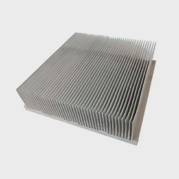
Oversized heat sinks face challenges. Airflow may bypass the fin structure, reducing heat transfer. Large fins can create stagnant zones, trapping warm air. Heat must travel through the material first. If thermal path is long, the core device can get hotter. Designers must match size with airflow and fin spacing. Material cost also rises with size, sometimes unnecessarily. Oversized heat sinks increase weight, adding stress to assemblies. Additionally, large heat sinks can interfere with other devices or airflow channels. Therefore, optimization requires understanding heat source, material, and environment, not just size.
Effects of oversizing table
| Oversizing Effect | Result |
|---|---|
| Restricted airflow | Less effective cooling |
| Increased weight | PCB stress or mounting issues |
| Long thermal path | Slower heat transfer |
| Higher cost | Not justified by performance gain |
Engineers sometimes use simulation or computational fluid dynamics to identify the right balance. A smaller heat sink with optimized fin pattern can outperform a bulky one. Overengineering can waste material and reduce thermal efficiency.
Additional considerations
- Fins must allow air to pass easily.
- Oversized heat sinks need strong mounting.
- Cost-benefit analysis helps decide maximum practical size.
- Material selection is critical; copper and aluminum behave differently.
What cooling requirements determine heat sink size?
The right size depends on how much heat the device produces and how it will be cooled. Power, ambient temperature, and airflow guide the decision.
Cooling requirements like device power, operating temperature, and airflow directly determine the needed heat sink size. Designers calculate thermal resistance to meet these requirements.
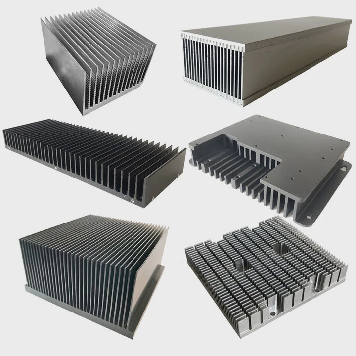
To determine size, start with the device’s power dissipation. High-power devices need low thermal resistance heat sinks. Ambient conditions matter too. Hot environments require more cooling than cooler ones. Airflow type influences selection. Natural convection requires larger surface area than forced air. Engineers calculate required thermal resistance using formulas like:
[ R{th} = \frac{T{device} - T_{ambient}}{P} ]
Where (T{device}) is maximum device temperature, (T{ambient}) is surrounding air temperature, and (P) is power in watts. Designers use this to choose material, size, and fin design. Some systems use active cooling, which may allow smaller heat sinks. Others use passive cooling, needing larger or more efficient heat sinks.
Thermal calculation example
| Device Power (W) | Max Temp (°C) | Ambient (°C) | Required Rth (°C/W) |
|---|---|---|---|
| 50 | 85 | 25 | 1.2 |
| 100 | 90 | 30 | 0.6 |
| 200 | 100 | 35 | 0.325 |
Proper sizing also depends on system layout. Heat sinks near hot components may need more clearance. Some designs combine heat pipes, fans, or liquid cooling. Each method changes the size requirements. Thermal interface material matters too; poor contact can make a perfectly sized heat sink ineffective. Ultimately, cooling requirements guide the maximum practical size, balancing performance, space, and cost.
Practical design checklist
- Calculate device heat dissipation.
- Consider ambient temperature.
- Determine airflow availability.
- Select material with high thermal conductivity.
- Optimize fin design for airflow.
- Confirm mechanical constraints are met.
Conclusion
Maximum heat sink size is not simply the biggest one that fits. It is set by space, airflow, weight, and cooling needs. Proper design and optimization matter more than size alone.