A Power Transistor Mounted on a Finned Heat Sink?
- Yongxing
- 19 Mar ,2026
Hot devices fail fast. Many systems lose efficiency because heat stays trapped. This creates risk, short life, and unstable performance.
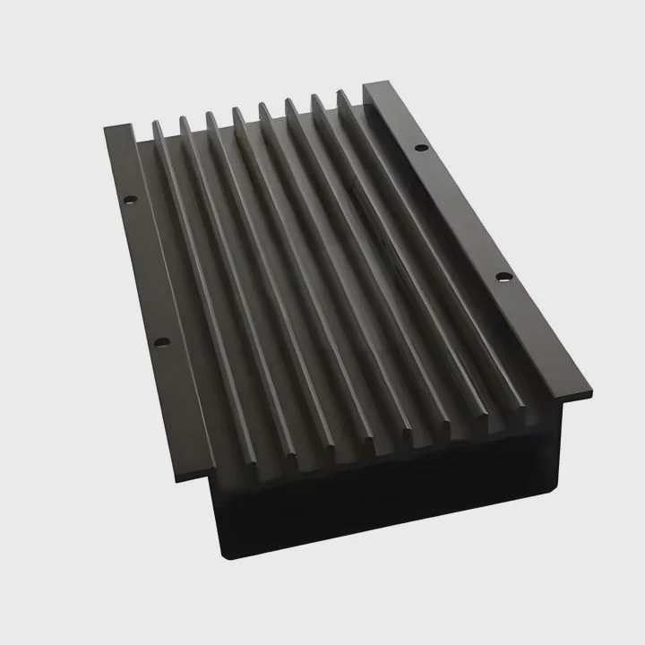
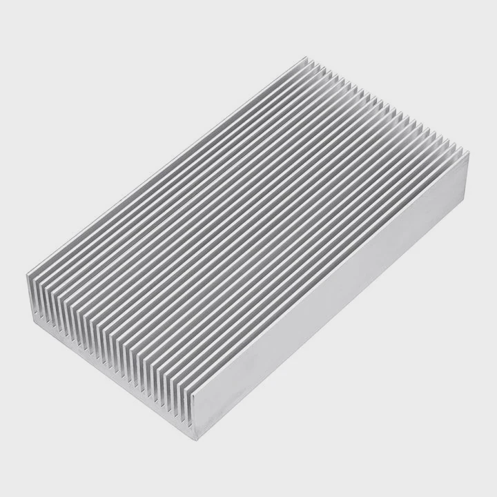
A power transistor is mounted on a finned heat sink to remove heat quickly. The fins increase surface area, which helps air carry heat away. This keeps the transistor within safe temperature limits and improves reliability.
Heat control is not optional in power electronics. It is a core part of design. The right heat sink design decides whether a system works or fails over time.
How do fins improve transistor cooling?
Heat builds up fast in power transistors. Without a path to escape, temperature rises quickly. This leads to reduced performance and early failure.
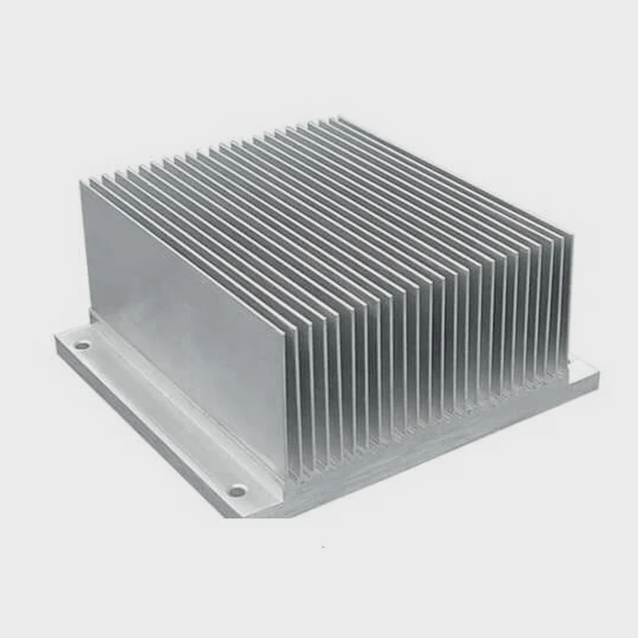
Fins improve cooling by increasing surface area. More surface means more contact with air. This allows heat to move away faster through convection and radiation.
Fins are simple in shape but powerful in function. A flat metal block can only release a limited amount of heat. When fins are added, the total surface area increases many times. This creates more contact between the heat sink and the surrounding air.
How surface area changes heat transfer
Heat transfer depends on three main factors:
- Surface area
- Temperature difference
- Air flow
Fins mainly improve the first factor. When the area increases, more heat can leave the surface at the same time.
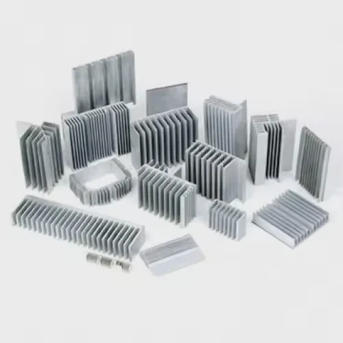
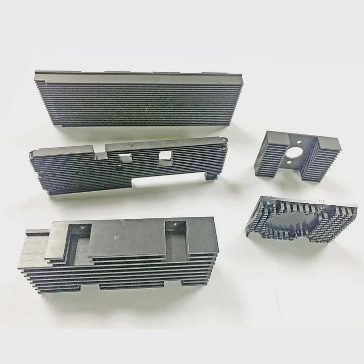
Types of fin designs
Different fin shapes are used based on airflow and space:
| Fin Type | Description | Use Case |
|---|---|---|
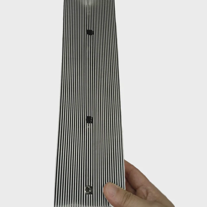
| Straight fins | Parallel lines, simple design | Natural convection systems |
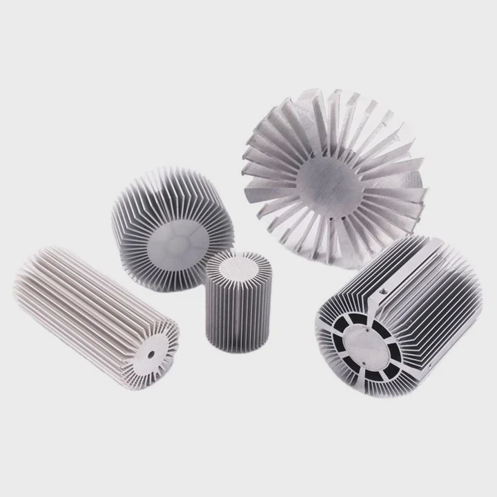
| Pin fins | Cylindrical or square pins | Multi-direction airflow |
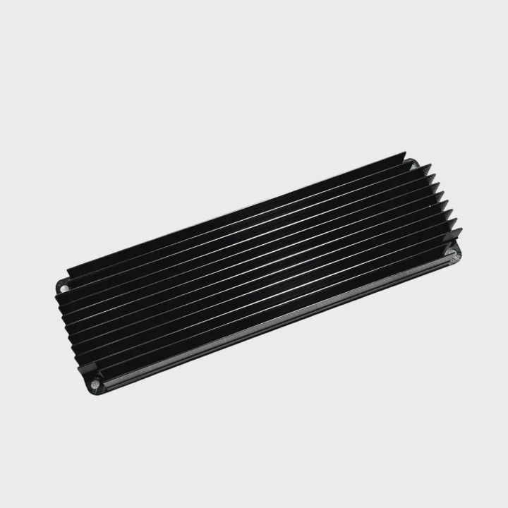
| Skived fins | Thin, dense fins cut from block | High-performance applications |
| Folded fins | Thin sheets folded into shape | Lightweight and cost-effective |
Each design changes how air moves through the heat sink. For example, pin fins allow air to flow from many directions. Straight fins work well when airflow is fixed in one direction.
Airflow matters
Fins alone are not enough. Air must move across them. There are two main methods:
- Natural convection (no fan)
- Forced convection (with fan)
Natural convection is simple but less powerful. Forced convection increases cooling performance but adds cost and complexity.
Real design thinking
In many projects, engineers do not just add more fins. They must balance:
- Weight
- Size
- Cost
- Thermal performance
Too many fins can block airflow. Too few fins reduce cooling. So the spacing and thickness must be optimized.
From experience, a well-designed fin structure can reduce transistor temperature by 20–40°C. This difference can double or triple the device lifetime.
Why are finned heat sinks widely used?
Many cooling methods exist. However, finned heat sinks remain one of the most common solutions. This is not by chance.
Finned heat sinks are widely used because they are simple, reliable, and cost-effective. They provide strong cooling performance without complex systems like liquid cooling.
Finned heat sinks offer a balance between performance and practicality. They do not require pumps, fluids, or sealed systems. This reduces failure points.
Key advantages
Here are the main reasons they are popular:
| Advantage | Explanation |
|---|---|
| Passive cooling | No moving parts needed in many cases |
| Low cost | Easy to manufacture in large volumes |
| High reliability | Fewer components mean fewer failures |
| Flexible design | Can be customized for different shapes and sizes |
| Easy integration | Simple to mount onto devices |
These features make them suitable for many industries.
Comparison with other cooling methods
| Cooling Method | Pros | Cons |
|---|---|---|
| Air (fins) | Simple, low cost | Limited for very high power |
| Liquid cooling | High efficiency | Complex, expensive |
| Heat pipes | Good heat spreading | Higher cost |
| Vapor chamber | Very high performance | Complex manufacturing |
Finned heat sinks sit in the middle. They are not the most powerful, but they are the most practical for many uses.
Scalability
Another reason for wide use is scalability. A design can be easily adjusted:
- Add more fins
- Increase size
- Use better materials
This allows engineers to adapt the same concept for small electronics or large industrial systems.
Real-world perspective
In many real projects, cost and reliability matter more than extreme performance. A finned heat sink often provides enough cooling without overdesign.
Many customers prefer a solution that is:
- Easy to produce
- Easy to test
- Easy to replace
This is why finned heat sinks remain the first choice in most power electronics systems.
Where are finned heat sinks installed in circuits?
Heat sinks are not random parts. They are placed exactly where heat is generated. In circuits, this usually means power components.
Finned heat sinks are installed directly on heat-generating components such as power transistors, MOSFETs, IGBTs, and voltage regulators to control temperature and ensure stable operation.
Common mounting locations
Heat sinks are typically attached to:
- Power transistors
- MOSFETs
- IGBT modules
- Voltage regulators
- Power diodes
These components handle high current and voltage. This leads to heat generation.
Mounting methods
There are several ways to install a heat sink:
| Method | Description | Application |
|---|---|---|
| Screw mounting | Bolted to component | High power devices |
| Clip mounting | Spring clips hold heat sink | Consumer electronics |
| Adhesive bonding | Thermal glue or tape | Lightweight applications |
| Soldering | Direct attachment in PCB | Compact designs |
Each method affects thermal resistance. A poor connection can reduce cooling efficiency.
Thermal interface materials (TIM)
Between the transistor and heat sink, a thermal interface is used. This fills air gaps.
Common TIM options:
- Thermal grease
- Thermal pads
- Phase change materials
These materials improve heat transfer from the device to the heat sink.
Circuit-level thinking
Placement is not only mechanical. It also affects airflow inside the system.
Engineers consider:
- Airflow direction
- Nearby components
- Heat accumulation zones
A poorly placed heat sink can trap heat instead of removing it.
Example scenario
In a power supply unit:
- Transistors are mounted on aluminum heat sinks
- A fan pushes air across fins
- Heat exits through vents
This creates a controlled thermal path.
From experience, even a good heat sink fails if airflow design is ignored. So placement and system design must work together.
Which materials are used for finned heat sinks?
Material choice is critical in heat sink design. It directly affects thermal performance, weight, and cost.
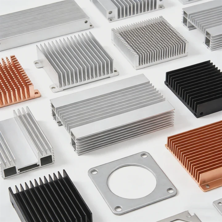
Finned heat sinks are mainly made from aluminum and copper. Aluminum is lightweight and cost-effective, while copper offers higher thermal conductivity but is heavier and more expensive.
Common materials
| Material | Thermal Conductivity | Weight | Cost | Typical Use |
|---|---|---|---|---|
| Aluminum | Medium (~200 W/m·K) | Light | Low | Most applications |
| Copper | High (~400 W/m·K) | Heavy | High | High-performance systems |
| Aluminum alloys | Slightly lower | Light | Moderate | Structural heat sinks |
Why aluminum is most used
Aluminum offers a strong balance:
- Good thermal performance
- Low weight
- Easy to machine or extrude
- Lower cost
This makes it ideal for mass production.
When copper is used
Copper is chosen when performance is critical:
- High power density systems
- Limited space
- Need for fast heat spreading
However, copper is heavier and harder to process.
Hybrid designs
Many modern heat sinks combine materials:
- Copper base + aluminum fins
- Vapor chamber + aluminum structure
This approach improves performance while controlling cost.
Manufacturing methods
Material choice also depends on production method:
| Process | Suitable Material | Features |
|---|---|---|
| Extrusion | Aluminum | Cost-effective, simple shapes |
| CNC machining | Aluminum/Copper | High precision |
| Skiving | Copper/Aluminum | High fin density |
| Die casting | Aluminum alloys | Complex shapes |
| Bonded fins | Both | Flexible design |
Surface treatment
Heat sinks often receive surface treatments:
- Anodizing (for aluminum)
- Nickel plating (for copper)
These improve corrosion resistance and sometimes thermal radiation.
Practical insight
Material selection is never only about conductivity. Engineers must consider:
- Budget
- Weight limits
- Production volume
- Application environment
In many projects, aluminum wins because it meets most needs at a reasonable cost.
Conclusion
Finned heat sinks help power transistors stay cool, stable, and reliable. They balance cost, performance, and simplicity. With proper design, placement, and material choice, they remain a core solution in modern thermal management.