How Does Heat Transfer in Heat Sink?
- Yongxing
- 06 May ,2026
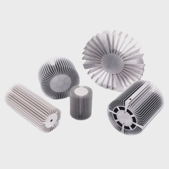
Heat buildup can damage electronics fast. Many systems fail because heat does not move away in time. Poor thermal control also cuts product life and lowers system stability.
Heat transfer in a heat sink works through conduction, convection, and radiation. Heat moves from the hot device into the heat sink base, spreads through the fins, and then transfers into the surrounding air or liquid. Efficient heat sinks depend on material, surface area, airflow, and structural design.
Modern electronics produce more heat than before. Power density keeps rising in EV systems, 5G equipment, industrial control units, and semiconductor modules. Because of this, thermal management is now part of product performance, not just product protection. A well-designed heat sink helps maintain stable temperatures, longer service life, and reliable output under heavy loads.
What Mechanisms Drive Heat Transfer in Sinks?
Heat inside a heat sink moves because thermal energy always travels from a hotter area to a cooler area. This process sounds simple, but several transfer mechanisms work together at the same time.
Heat transfer inside a heat sink mainly depends on conduction, convection, and radiation. Conduction moves heat through solid metal. Convection removes heat into air or liquid. Radiation releases a smaller amount of heat through electromagnetic waves.
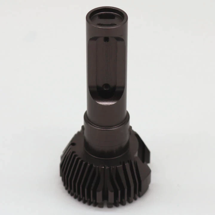
The first step starts at the heat source. This source may be a power module, CPU, IGBT, laser device, or battery system. The device surface becomes hot during operation. The heat sink touches this hot surface directly or through a thermal interface material.
Heat Conduction Starts First
Conduction happens inside solid materials. The thermal energy travels from molecule to molecule through the metal structure.
Aluminum and copper are common heat sink materials because they conduct heat very well. Copper transfers heat faster, but aluminum offers lower weight and lower cost. Many thermal systems combine both materials to balance performance and manufacturing cost.
Here is a simple comparison:
| Material | Thermal Conductivity | Weight | Cost |
|---|---|---|---|
| Aluminum | Good | Light | Lower |
| Copper | Excellent | Heavy | Higher |
| Vapor Chamber | Very High Equivalent Transfer | Medium | Higher |
The heat first enters the base plate. Then it spreads outward into the fins or thermal channels.
Convection Removes the Heat
After heat reaches the fins, the next stage begins. The surrounding air absorbs the heat from the metal surface.
This process is called convection.
Natural convection uses only surrounding airflow. Hot air rises naturally, and cooler air replaces it. This method works for lower-power systems.
Forced convection uses fans, blowers, or liquid pumps. This method increases cooling speed and supports higher heat loads.
In many high-power applications, forced airflow becomes necessary because natural airflow alone cannot remove enough heat.
Radiation Plays a Smaller Role
Every hot object emits thermal radiation. Heat sinks also release some heat through infrared energy.
Radiation contributes less than conduction and convection in most industrial systems. Still, black anodized surfaces can improve radiation performance slightly.
Different Systems Use Different Mechanisms
Some systems rely more on one transfer method than another.
| Cooling Type | Main Heat Transfer Mechanism | Typical Applications |
|---|---|---|
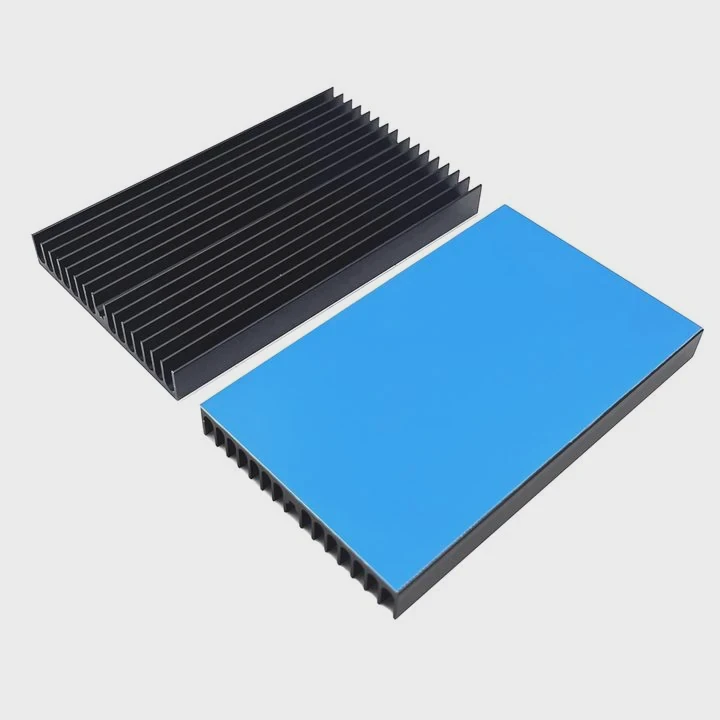
| Extruded Heat Sink | Conduction + Air Convection | Power supplies, LED systems |
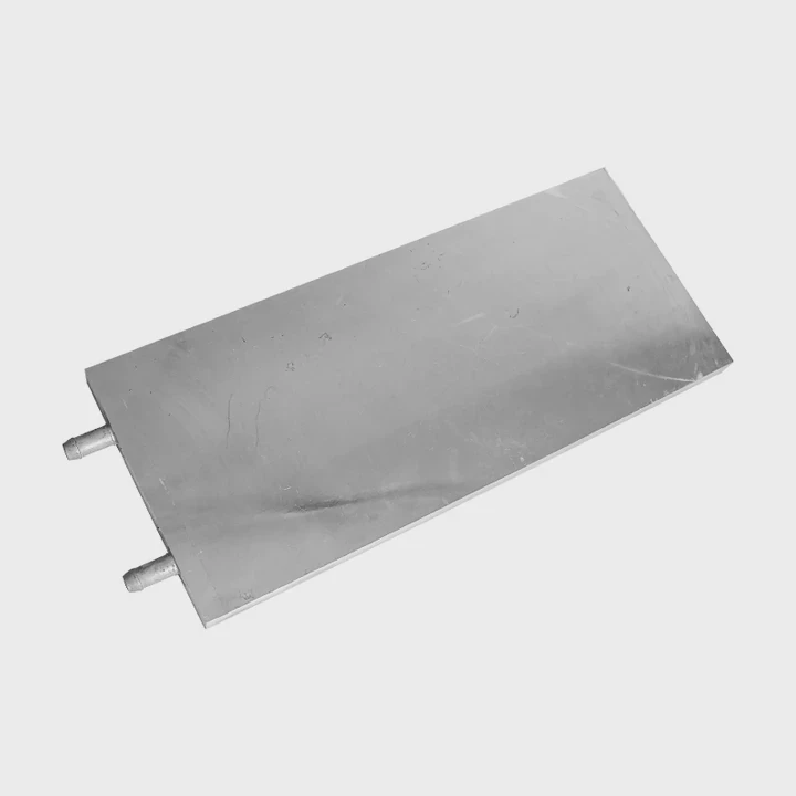
| Liquid Cooling Plate | Conduction + Liquid Convection | EV battery systems |
| Vapor Chamber | Phase Change + Conduction | High-power electronics |
| Skived Fin Heat Sink | Enhanced Air Convection | Telecom equipment |
Heat sink performance improves when all mechanisms work together smoothly. Weakness in one stage reduces total thermal efficiency.
Why Are Conduction and Convection Important?
Many engineers focus on airflow first. Others focus only on metal materials. In reality, both conduction and convection must work together. If one side performs poorly, the entire cooling system suffers.
Conduction spreads heat inside the heat sink, while convection removes that heat into the surrounding environment. Strong thermal performance needs both processes to stay balanced and efficient.

A heat sink acts like a bridge between the heat source and the outside air. The bridge fails if heat cannot travel smoothly across both stages.
Poor Conduction Creates Thermal Bottlenecks
Heat enters the base first. If the base material cannot spread heat evenly, hot spots appear quickly.
Hot spots create several problems:
- Reduced electronic performance
- Faster material aging
- Thermal stress
- Solder fatigue
- Component failure
This problem becomes serious in semiconductor modules and power electronics.
Thermal Resistance Matters
Engineers often discuss thermal resistance. Lower thermal resistance means heat moves more easily.
Several factors affect conduction resistance:
Material Quality
Pure copper conducts heat better than most aluminum alloys. Still, aluminum remains popular because it balances cost and weight.
Base Thickness
A thicker base spreads heat better, but too much thickness adds weight and slows response speed.
Interface Contact
Microscopic air gaps between the heat source and heat sink reduce transfer efficiency. Thermal grease or phase-change materials help fill those gaps.
Convection Determines Final Heat Removal
Even with excellent conduction, the system still overheats if airflow is weak.
Convection depends heavily on surface exposure.
More fin area means more contact between metal and air. This allows more heat to escape.
Airflow Design Changes Everything
Fin geometry affects airflow resistance and cooling efficiency.
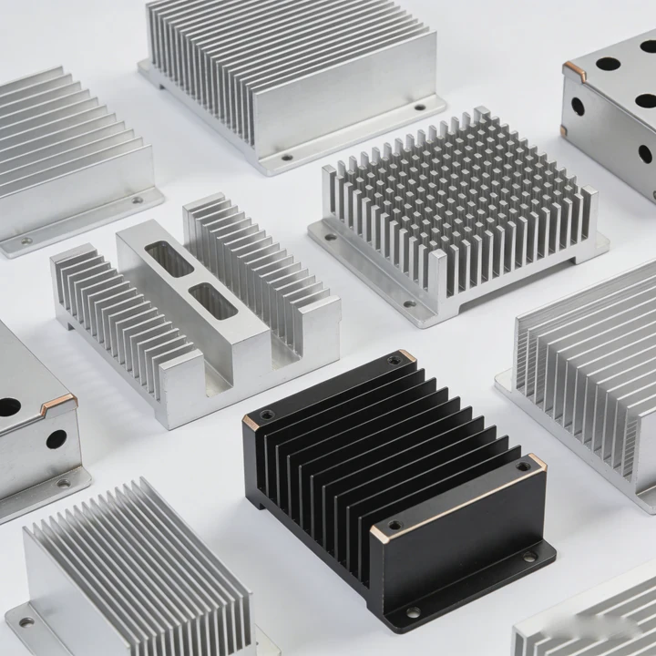
Common designs include:
- Straight fins
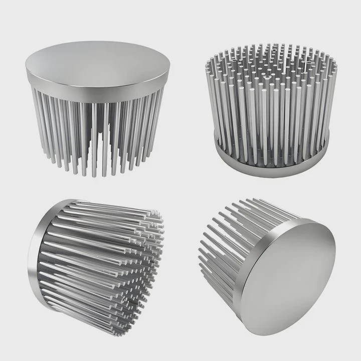
- Pin fins
- Folded fins
- Skived fins
Each design fits different airflow conditions.
For example:
| Fin Type | Best Condition | Main Benefit |
|---|---|---|
| Straight Fin | Directed airflow | Simple manufacturing |
| Pin Fin | Multi-direction airflow | Better turbulence |
| Skived Fin | High-density cooling | Thin fin spacing |
| Folded Fin | Lightweight systems | Large surface area |
Forced Cooling Increases Performance
Fans increase air velocity across the fins. Faster airflow improves convection dramatically.
Still, stronger airflow also increases:
- Noise
- Dust buildup
- Power use
- Maintenance needs
Because of this, thermal engineers balance cooling performance with long-term reliability.
In many rail transit and energy storage systems, liquid cooling replaces air cooling because heat density becomes too high for standard convection methods.
Where Does Heat Flow Within the Heat Sink?
Many people think heat spreads evenly inside the heat sink. In reality, heat follows specific thermal paths based on resistance and geometry.
Heat flows from the heat source into the heat sink base, then spreads through the metal structure toward the fins, where it transfers into surrounding air or liquid. The flow path depends on material conductivity, fin design, and cooling conditions.
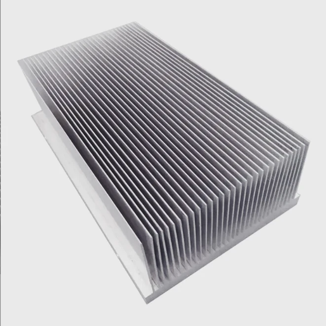
Understanding heat flow helps engineers improve thermal performance and reduce wasted material.
Heat Starts at the Contact Surface
The first contact area is critical.
If the mounting surface is uneven, heat transfer becomes unstable. Surface flatness directly affects thermal contact resistance.
High-power systems often use:
- CNC-machined contact surfaces
- Thermal pads
- Graphite sheets
- Solder interfaces
- Phase-change materials
These methods improve contact efficiency.
The Base Spreads the Heat
After entering the base, heat begins spreading sideways.
This stage is called heat spreading.
A narrow heat source creates concentrated thermal density. The base must distribute this energy evenly before it reaches the fins.
Heat Moves Toward Cooler Regions
Heat naturally follows the path of least thermal resistance.
This means:
- Heat travels faster through copper than aluminum
- Thick regions store more heat temporarily
- Thin fins release heat faster
The design must balance spreading ability with heat release speed.
Fin Structures Guide Heat Flow
Fins are not just surface extensions. They control airflow interaction and heat distribution.
Tall fins increase surface area. Thin fins improve air contact. Dense fins increase cooling area but may reduce airflow efficiency if spacing becomes too narrow.
Heat Distribution Is Never Perfect
In real applications, temperature varies across the heat sink.
The hottest region usually stays near the heat source.
Thermal simulation software helps engineers predict:
- Temperature gradients
- Airflow paths
- Hotspot locations
- Pressure drop
- Thermal resistance
Vapor Chambers Change the Flow Pattern
Advanced heat sinks use vapor chambers or heat pipes.
These systems use phase change to move heat quickly across wider areas.
Inside the chamber:
- Liquid absorbs heat
- Liquid evaporates
- Vapor spreads rapidly
- Vapor condenses in cooler areas
- Liquid returns through capillary action
This process spreads heat much faster than solid metal alone.
Liquid Cooling Changes Heat Flow Again
Liquid cooling plates guide heat into flowing coolant channels.
The coolant carries heat away continuously.
This method supports:
- EV battery systems
- Energy storage equipment
- High-power lasers
- Data centers
- Railway electronics
Liquid cooling reduces thermal resistance significantly under high power loads.
Which Factors Influence Transfer Efficiency?
Even a large heat sink may perform poorly if several design details are wrong. Heat transfer efficiency depends on many connected factors.
Heat transfer efficiency depends on material conductivity, surface area, airflow, fin geometry, interface quality, ambient temperature, and manufacturing precision. Optimizing all factors together produces better thermal performance and system reliability.
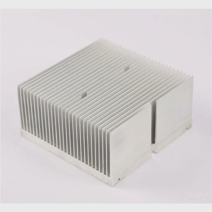
Many thermal failures come from small design mistakes rather than one major issue.
Material Selection Is Critical
Material properties affect heat movement immediately.
Copper offers higher thermal conductivity, but aluminum provides:
- Lower cost
- Easier machining
- Lower weight
- Better corrosion resistance in some conditions
Hybrid structures often combine both materials.
Surface Area Directly Affects Cooling
Larger surface area improves convection.
This explains why heat sinks use fins instead of flat blocks.
Still, more fins do not always mean better cooling.
Very dense fins may trap airflow and increase pressure drop.
Airflow Conditions Matter
Cooling efficiency changes based on airflow direction and speed.
Important airflow factors include:
Air Velocity
Faster air removes heat more quickly.
Air Temperature
Cooler incoming air increases thermal difference and improves heat transfer.
Air Distribution
Uneven airflow creates local hotspots.
Contact Resistance Reduces Efficiency
Poor mounting pressure creates microscopic gaps.
Air trapped in those gaps acts as insulation.
Thermal interface materials help reduce this problem.
Common materials include:
- Thermal grease
- Thermal pads
- Graphite sheets
- Phase-change compounds
Manufacturing Quality Affects Thermal Stability
Precision matters in thermal systems.
Small variations in:
- Flatness
- Brazing quality
- Welding quality
- Fin alignment
- Surface finish
can change thermal resistance noticeably.
In high-reliability sectors like rail transit and aerospace, manufacturers perform thermal cycling and vibration tests to confirm long-term stability.
Environment Also Changes Performance
Operating conditions strongly affect cooling behavior.
A heat sink inside a clean laboratory performs differently from one inside a dusty industrial cabinet.
Important environmental factors include:
| Environmental Factor | Effect on Heat Transfer |
|---|---|
| High Ambient Temperature | Reduces cooling capacity |
| Dust Accumulation | Blocks airflow |
| Humidity | May increase corrosion |
| Vibration | Can weaken thermal interfaces |
| Altitude | Reduces air density and convection |
System-Level Design Is Necessary
A heat sink alone cannot solve every thermal issue.
The full system design must consider:
- Air channel layout
- Fan placement
- Power density
- Enclosure size
- Thermal cycling conditions
Modern thermal management often combines multiple technologies together:
- Heat sinks
- Vapor chambers
- Heat pipes
- Liquid cooling plates
- Thermal interface materials
- Smart thermal monitoring
This integrated approach improves both cooling performance and long-term reliability.
Conclusion
Heat transfer in a heat sink depends on conduction, convection, and careful thermal design. Efficient systems move heat quickly from the source into the surrounding environment. Material choice, airflow, fin structure, and manufacturing precision all play major roles in keeping modern electronics safe, stable, and reliable.