How Does the Heat Sink Work?
- Yongxing
- 13 Mar ,2026
Heat builds fast inside modern devices. When that heat stays trapped, performance drops, parts age early, and sudden failure becomes a real risk.
A heat sink works by pulling heat away from a hot component, spreading that heat across a larger metal surface, and releasing it into the surrounding air or liquid. Its shape, material, and airflow all decide how well it performs.
That basic idea sounds simple, but the real story is more useful. A heat sink is not just a piece of metal on top of a chip. It is part of a full heat path. Every step in that path matters, from the chip surface to the base, fins, air, and the space around the device.
What Mechanisms Allow Heat Sinks to Cool Devices?
Heat can ruin device life in quiet ways. A unit may still run, but it may run slower, drift out of spec, or fail much sooner than expected. That is why the cooling path must be understood, not guessed.
Heat sinks cool devices through conduction, heat spreading, convection, and sometimes radiation. First, heat moves from the chip into the heat sink base. Next, it spreads through the metal. Then, air or liquid carries it away from the fins and outer surfaces.
A heat sink works because heat always moves from a hotter place to a cooler one. In electronics, the chip or power module becomes the hot source. The heat sink becomes the bridge between that hot source and the cooler outside environment.
Conduction starts the process
The first step is conduction. This means heat moves through solid materials. The chip package touches a thermal interface material, and that layer touches the heat sink base. If this contact is poor, the rest of the system cannot save it. Even a strong heat sink will struggle when the contact area is uneven or when air gaps stay between surfaces.
A good design reduces contact resistance. Flatness matters. Mounting pressure matters. The thermal interface material matters too. These details often decide whether the device runs safely or too hot.
Heat spreading reduces hot spots
After heat enters the base, it needs to spread out. This is important because chips create heat in a small area, but the fins offer a much larger area. The base acts like a traffic distributor. It moves heat from the small footprint of the chip to a wider area under the fins.
If the base is too thin, heat may stay crowded near the source. If it is too thick, the design may gain weight and cost without enough benefit. Good heat sink design balances both.
Convection removes most of the heat
Once heat reaches the fins, convection takes over. This is where moving air or liquid carries heat away from the surface. In passive cooling, natural air movement does the job. Hot air rises, and cooler air replaces it. In active cooling, a fan pushes more air across the fins and improves heat removal.
The bigger the useful surface area, the more heat can leave the sink. That is why fins are common. They increase the contact area between the metal and the air.
Radiation helps, but less than many think
All hot surfaces also release some heat by radiation. This part is usually smaller than conduction and convection in most electronic products. Still, surface finish can have some effect, especially in designs with limited airflow.
| Mechanism | What it does | Why it matters |
|---|---|---|
| Conduction | Moves heat from chip to sink | Starts the heat path |
| Heat spreading | Distributes heat across the base | Reduces local hot spots |
| Convection | Transfers heat from fins to air or liquid | Removes most of the heat |
| Radiation | Emits heat from the surface | Adds a smaller extra effect |
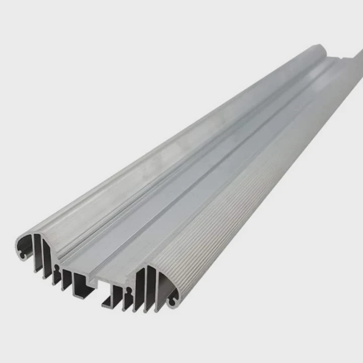
A heat sink does not “destroy” heat. It only moves heat to a place where the environment can absorb it. That is the core idea behind every heat sink, from a simple aluminum profile to a more complex liquid-cooled assembly.
Why Does Thermal Conductivity Matter?
Many cooling problems begin with a wrong material choice. A heat sink may look large and solid, but if heat cannot move through it fast enough, the hot spot stays near the source and the full surface never gets used.
Thermal conductivity matters because it shows how easily heat moves through a material. A higher conductivity helps the heat sink spread heat faster and more evenly, which lowers hot spots and improves the use of fins and surface area.
Thermal conductivity is one of the first properties many engineers check, and for good reason. A heat sink does not help much if it traps heat near the chip instead of moving it outward. This is why copper and aluminum are used so often in thermal products.
Why heat flow inside the metal matters
When heat enters the base, it needs a fast path. If the material resists heat flow, the area right above the chip gets very hot while the outer fins stay cooler than they should. That means a large part of the sink is underused.
This issue matters even more in high-power devices, where heat density is high. A small source with high wattage can produce a sharp local hot spot. Better conductivity helps flatten that temperature difference.
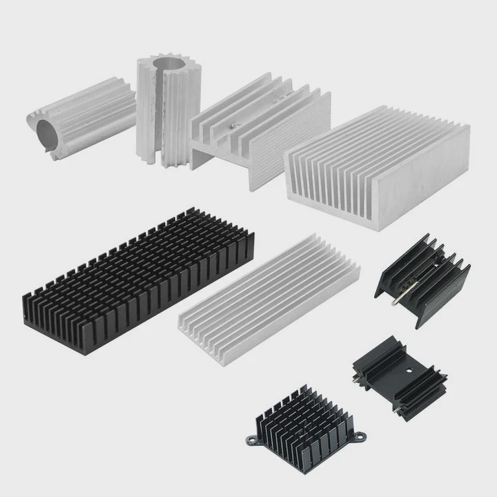
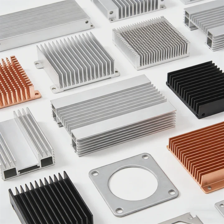
Copper and aluminum each solve a different problem
Copper has higher thermal conductivity than aluminum. So, copper spreads heat better. That is useful when the heat source is small and intense. But copper is heavier and more expensive. Aluminum has lower conductivity, yet it is lighter, easier to extrude, and often more cost-effective for large fin structures.
That is why many real products combine both. A copper base may sit under aluminum fins. This gives faster spreading near the source and lower weight in the larger structure.
Conductivity is important, but it is not the only factor
Some buyers focus only on the conductivity number. That can be a mistake. A high-conductivity material cannot fix poor airflow, weak fin design, or bad mounting. The full thermal path still matters.
A practical design looks at these points together:
Material selection checklist
- Heat load
- Heat source size
- Weight target
- Cost target
- Corrosion needs
- Manufacturing method
- Airflow conditions
| Material | Relative thermal performance | Typical strength in design | Main trade-off |
|---|---|---|---|
| Aluminum | Good | Light weight, cost control, easy fin shapes | Lower conductivity than copper |
| Copper | Very high | Strong heat spreading near hot spots | Higher weight and cost |
| Hybrid design | Very good | Balanced performance and structure | More complex manufacturing |
Thermal conductivity matters because it decides how much of the heat sink can truly join the job. In simple terms, a better heat path inside the metal gives the outside surface a better chance to release heat.
Where Is Heat Transferred After Leaving Chips?
Many people stop the story at the heat sink. They picture heat entering the metal and assume the problem is solved there. It is not. The heat sink is only one stop in the journey. The heat still has to leave the system.
After leaving chips, heat moves into the thermal interface layer, then into the heat sink base and fins, and finally into the surrounding air or cooling liquid. From there, it spreads into the wider environment outside the device enclosure.
The full heat path is one of the most useful ways to understand thermal design. When a device overheats, the real cause may be anywhere along that path, not only at the chip.
Step 1: From the chip to the package
The chip creates heat inside a very small area. That heat first moves through the semiconductor package. This internal path depends on chip layout, die attach, package material, and internal thermal resistance. At this stage, the external heat sink has not even started working yet.
Step 2: Across the interface
Then the heat reaches the outer surface and crosses into a thermal interface material. This layer fills tiny gaps between the two surfaces. Without it, trapped air would block heat transfer because air conducts heat poorly.
This step often decides whether a design performs as expected in real assembly. A good CAD model can still lead to poor results if mounting pressure is uneven or the interface material is chosen badly.
Step 3: Through the heat sink body
Now the heat enters the heat sink base and moves outward into the fins or channels. This is where spreading becomes important. The heat sink must avoid crowding heat in one zone while leaving the rest cool.
Step 4: Into air or liquid
After that, heat leaves the metal surface and enters the coolant. In many products, the coolant is air. In higher-power systems, it may be water-glycol or another controlled fluid. If air inside the enclosure is already hot and stagnant, the heat sink loses strength because the temperature difference becomes smaller.
Step 5: Out of the enclosure and into the room or outside system
The final step is easy to forget. Heat must still leave the enclosure, rack, cabinet, or machine. A strong heat sink inside a poorly ventilated box can only do so much. In larger systems, the heat may then move into facility air, a building cooling loop, or an outdoor heat rejection unit.
A simple heat path view
Local path
Chip → package → interface material → heat sink base
Release path
Heat sink fins or channels → air or liquid → enclosure or piping → external environment
This wider view explains why thermal design is a system problem. A strong chip cooler with weak cabinet airflow can still fail. A good liquid cold plate with poor pump flow can also fail. Heat only leaves when every link in the chain works together.
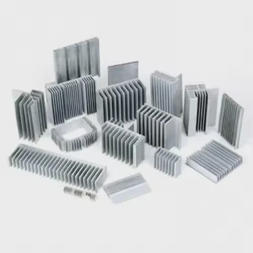
Which Structures Enhance Heat Sink Efficiency?
A heat sink can be made from good metal and still perform poorly if the structure wastes airflow or surface area. Shape changes performance in a direct way. That is why geometry is not decoration. It is the heart of thermal efficiency.
Heat sink efficiency improves when the structure increases useful surface area, spreads heat evenly, supports smooth airflow, and matches the real heat load. Common high-efficiency features include fins, pins, vapor chambers, heat pipes, and optimized base thickness.
Structure controls how heat moves and how air flows. A better structure does not always mean a more complex one. In many cases, the best design is the one that fits the heat source, airflow direction, space limit, and cost target with the least waste.
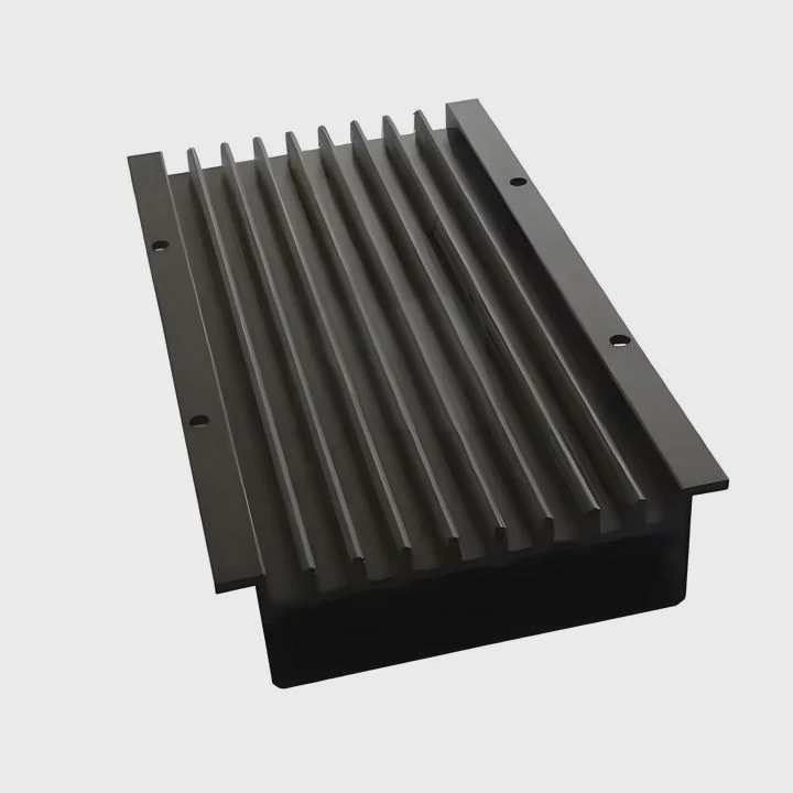
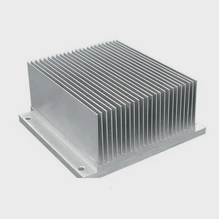
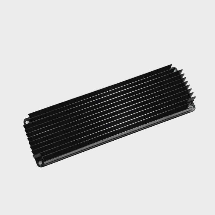
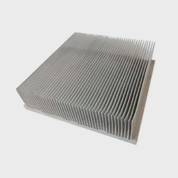
Fin structures
Straight fins are common because they are simple and effective when airflow has a clear direction. They work well in forced-air systems, such as fan-cooled electronics. Pin fins are more flexible when airflow direction is uncertain. Air can move around them from different angles, which helps in less controlled environments.
Fin spacing matters as much as fin count. More fins do not always mean better cooling. When the gap becomes too narrow, airflow resistance rises and useful heat transfer may drop.
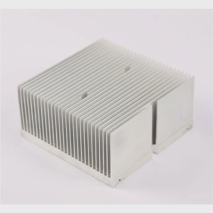
Base design
The base connects the heat source to the full structure. Its thickness affects spreading. A thin base may leave hot spots. A very thick base may add weight and cost. The right thickness depends on the source area and heat density.
Heat pipes and vapor chambers
When heat must move quickly from one place to another, advanced spreading structures help. Heat pipes use phase change inside a sealed tube to move heat with high efficiency. Vapor chambers do a similar job in a flatter form. These are useful when the heat source is compact but the cooling area is larger or offset.
Surface and airflow alignment
A strong structure also respects the real airflow path. In fan-cooled designs, fin direction should support the air route instead of blocking it. In passive systems, vertical orientation may help natural convection.
Structure comparison
| Structure | Best use case | Main benefit | Main limit |
|---|---|---|---|
| Straight fins | Directed airflow | Strong performance with fans | Less flexible with changing airflow |
| Pin fins | Multi-direction airflow | Good all-around air access | Can have higher pressure drop |
| Skived fins | High surface area designs | Thin dense fins possible | More cost than simple extrusion |
| Bonded fins | High-performance custom shapes | Flexible geometry | More assembly complexity |
| Heat pipes | Remote or fast heat spreading | Moves heat efficiently over distance | Added design complexity |
| Vapor chambers | Flat high-flux spreading | Great for hot spots | Higher cost |
Design choices that often improve efficiency
Match fin layout to airflow
A mismatch between fin direction and fan direction wastes cooling potential.
Increase real surface area, not just visual bulk
A large block of metal may look strong but do less than a lighter finned design.
Control pressure drop
Air must be able to move through the structure. Tight channels can choke the system.
Fit the source size
A tiny source under a wide sink needs good spreading support, not only bigger fins.
Keep manufacturing in view
The best thermal shape must still be manufacturable at stable quality and cost.
A useful heat sink is never just “bigger.” It is better matched. The best structure is the one that turns more of the material into active thermal surface while keeping heat flow and airflow smooth from start to finish.
Conclusion
A heat sink works by guiding heat through a clear path: away from the chip, through the metal, and into air or liquid. When material, structure, and airflow work together, cooling becomes stable, efficient, and easier to trust.