How to Calculate Heat Sink Size?
- Yongxing
- 22 Apr ,2026

Many systems overheat because the heat sink is too small. This leads to failure, short lifespan, and unstable performance.
Heat sink size is calculated by analyzing thermal load, allowable temperature rise, airflow, and thermal resistance to ensure the device stays within safe limits.
Sizing is not guesswork. It follows a clear method. Once the steps are clear, the design becomes predictable and repeatable.
What factors determine required heat sink size?
Heat sink sizing often fails because key factors are missed. Many designs only look at power and ignore system limits.
The required heat sink size depends on thermal load, allowable temperature rise, ambient conditions, airflow, and material thermal conductivity.
I always start by identifying all constraints. Heat sink size is not just about heat. It is about the full environment.
Key Factors That Control Size
1. Thermal Load (Power Dissipation)
This is the heat generated by the device.
- Measured in watts (W)
- Higher power needs larger heat sinks
2. Maximum Junction Temperature
Every component has a safe limit.
- Exceeding it causes damage
- This sets the upper boundary
3. Ambient Temperature
The surrounding air temperature matters.
- Higher ambient reduces cooling ability
- Outdoor systems need larger designs
4. Airflow Conditions
| Cooling Type | Impact on Size |
|---|---|
| Natural convection | Larger heat sink needed |
| Forced convection | Smaller heat sink possible |
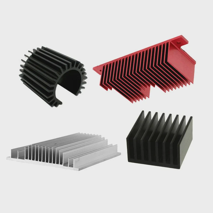
5. Material Properties
Different materials transfer heat differently.
Combined Effect
All these factors interact. A small change in one can change the final size.
For example:
- Increasing airflow can reduce size
- Raising ambient temperature increases size
Practical Insight
In one project, a system designed for 25°C ambient was moved to a 45°C environment. The original heat sink failed. We had to increase size by 40% to maintain safe operation.
Why is thermal load important in sizing?
Many engineers underestimate thermal load. That mistake leads to undersized heat sinks and overheating problems.
Thermal load defines how much heat must be removed. Without accurate thermal load, heat sink sizing cannot be correct.
Thermal load is the starting point of every calculation. Everything else depends on it.
Understanding Thermal Load
Thermal load is the total heat generated by the device.
- Usually equal to electrical power loss
- Measured in watts
Sources of Thermal Load
Electrical Losses
- Resistance heating
- Switching losses
Environmental Gains
- Nearby components
- Solar or external heat
Why Accuracy Matters
If thermal load is wrong:
- Heat sink will be too small or too large
- System cost and risk increase
Simple Estimation Method
| Parameter | Example Value |
|---|---|
| Input Power | 100 W |
| Efficiency | 90% |
| Heat Loss | 10 W |
Heat loss becomes thermal load.
Real Experience
I worked on a battery system where engineers only considered nominal load. But peak load was 2× higher. During operation, the system overheated. After recalculating with peak load, the correct heat sink size solved the issue.
Key Takeaway
Always design for worst-case thermal load, not average.
Where should calculations begin for sizing?
Many people jump into formulas too quickly. That leads to confusion and wrong results.
Heat sink sizing calculations should begin with defining thermal limits, including maximum junction temperature, ambient temperature, and allowable temperature rise.
I always begin with temperature targets. Without them, calculations have no direction.
Step-by-Step Starting Point
Step 1: Define Maximum Temperature
- Junction temperature (Tj max)
- Case temperature if needed
Step 2: Define Ambient Temperature (Ta)
- Real operating environment
- Worst-case scenario
Step 3: Calculate Allowable Temperature Rise
ΔT = Tj - Ta
This value defines how much heat can be safely dissipated.
Example Table
| Parameter | Value |
|---|---|
| Max junction temp | 125°C |
| Ambient temp | 40°C |
| Allowable rise (ΔT) | 85°C |
Step 4: Determine Thermal Resistance Target
Thermal resistance tells how effective the heat sink must be.
Lower resistance = better cooling.
Why This Order Matters
If you skip these steps:
- You may design blindly
- Results will not match real conditions
Real Case
In one inverter project, the team started with a standard heat sink size. But they ignored ambient conditions inside the enclosure. Internal temperature reached 60°C, not 25°C. After recalculating from correct starting values, the design changed completely.
Which formulas help calculate heat sink size?
Many people feel confused about formulas. But the core equations are simple and practical.
The main formula for heat sink sizing is thermal resistance: Rθ = ΔT / Q, which determines how large and efficient the heat sink must be.
This formula connects temperature, power, and design.
Core Formula
Thermal resistance equation:
Rθ = ΔT / Q
Where:
- Rθ = thermal resistance (°C/W)
- ΔT = temperature rise (°C)
- Q = thermal load (W)
How to Use It
Step 1: Input Known Values
- ΔT from earlier calculation
- Q from thermal load
Step 2: Solve for Rθ
This gives the required heat sink performance.
Step 3: Select or Design Heat Sink
Match Rθ with real product data.
Example Calculation
| Parameter | Value |
|---|---|
| ΔT | 80°C |
| Q | 20W |
| Rθ | 4°C/W |
This means the heat sink must have thermal resistance ≤ 4°C/W.
Extended Considerations
Total Thermal Path
Total resistance includes:
| Section | Resistance Type |
|---|---|
| Junction to case | Internal chip |
| Case to heat sink | Interface material |
| Heat sink to air | Main design target |
Real Design Adjustment
If total allowed Rθ = 4°C/W:
- Chip internal = 1°C/W
- Interface = 0.5°C/W
Then heat sink must be:
Rθ ≤ 2.5°C/W
Practical Insight
Many designs fail because engineers use the total Rθ directly for the heat sink. That is incorrect. The heat sink only handles part of the thermal path.
Final Tip
Always leave margin (10–20%) to ensure reliability.
Conclusion
Heat sink sizing follows a clear method. Define temperatures, calculate thermal load, apply resistance formulas, and match real conditions. A correct process ensures stable and reliable cooling performance.