how to size a heat sink?
- Yongxing
- 22 Apr ,2026
Thermal failure often starts silently. A small mistake in heat sink sizing can lead to overheating, reduced lifespan, or even system shutdown.
To size a heat sink, we calculate heat load, define temperature limits, estimate thermal resistance, and match a suitable heat sink design that meets performance and safety margins.
Once the basic idea is clear, the real challenge begins. Each step has hidden details that can make or break your design. Let’s go deeper.
What steps are used to size a heat sink?
Thermal issues often appear late in a project. Many engineers guess the heat sink size, then fix problems later. This wastes time and cost.
The key steps include defining power dissipation, setting temperature limits, calculating required thermal resistance, and selecting or designing a heat sink that meets those targets.
Sizing a heat sink follows a clear engineering path. However, each step must be done carefully.
Step 1: Define Power Dissipation
First, we identify how much heat the device generates. This is usually in watts (W). For example, a power module may generate 150W.
Step 2: Set Temperature Limits
We define:
- Maximum junction temperature (Tj max)
- Ambient temperature (Ta)
These values create the thermal window.
Step 3: Calculate Thermal Resistance
We use this simple formula:
Thermal Resistance (Rth) = (Tj max - Ta) / Power
This gives the total allowable resistance from junction to air.
Step 4: Break Down Thermal Path
The total resistance includes:
| Section | Description |
|---|---|
| Junction to case | Internal chip resistance |
| Case to interface | Thermal interface material |
| Heat sink to air | Heat sink performance |
We subtract known values to find the required heat sink resistance.
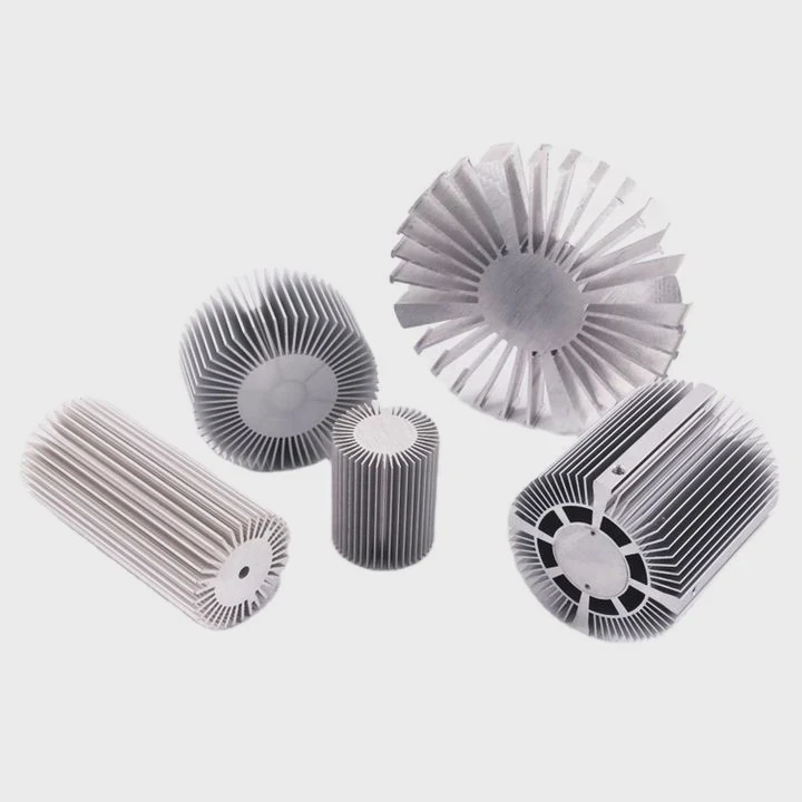
Step 5: Select Heat Sink Type
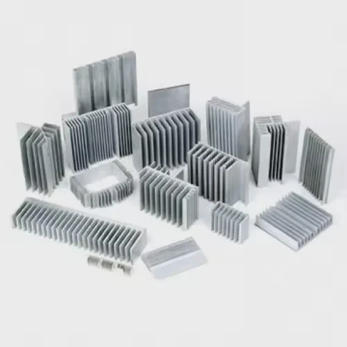
Now we choose:
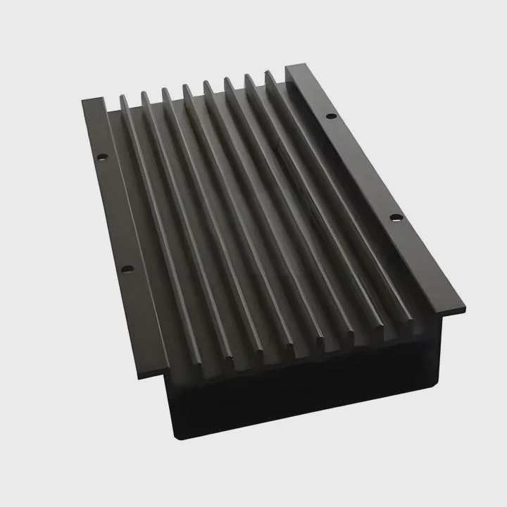
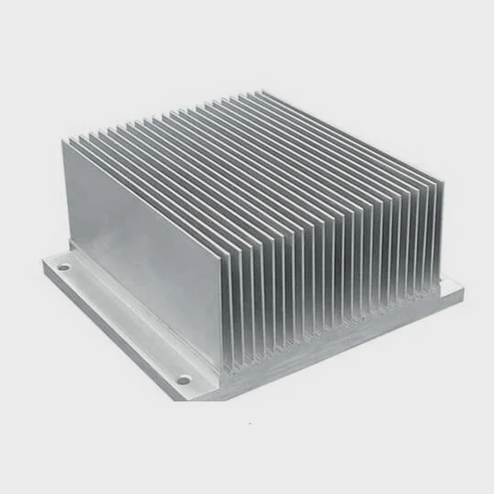
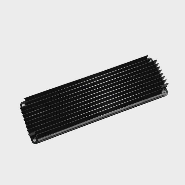
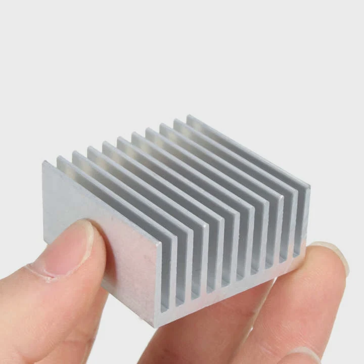
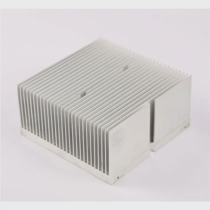
- Extruded aluminum heat sink
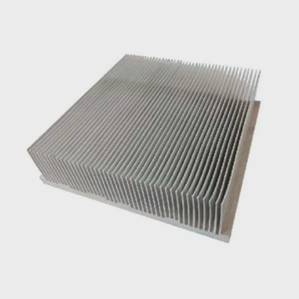
- Skived fin heat sink
- Liquid cooling plate
- Vapor chamber solution
Each option has different performance and cost.
Step 6: Validate Design
We use:
- Simulation (CFD)
- Prototyping
- Thermal testing
Why This Process Matters
Skipping steps leads to:
- Oversized heat sinks (high cost)
- Undersized heat sinks (failure risk)
A structured approach ensures balance between performance and cost.
Why does power dissipation affect sizing?
Many people underestimate power. They assume a small increase does not matter. In reality, even a small rise can drastically change heat sink size.
Power dissipation directly determines how much heat must be removed, and higher power requires lower thermal resistance, which leads to larger or more efficient heat sinks.
Power dissipation is the starting point of all thermal design.
Linear Relationship, Nonlinear Impact
Heat generation increases linearly. However, heat removal becomes harder as temperature rises.
This creates a design challenge.
Example Comparison
| Power (W) | Required Rth (°C/W) | Heat Sink Size Impact |
|---|---|---|
| 50W | 1.0 | Small |
| 100W | 0.5 | Medium |
| 200W | 0.25 | Large or advanced |
As power doubles, required thermal resistance halves.
Air Cooling Limits
Air cooling has limits:
- Natural convection works for low power
- Forced air extends capability
- Beyond that, liquid cooling is needed
Heat Flux Density
Not just total power matters. Power density also matters.
A small chip with high power:
- Creates hot spots
- Needs advanced solutions like vapor chambers
Material and Design Impact
Higher power requires:
- Better materials (copper, vapor chambers)
- More surface area
- Improved airflow design
Real-World Insight
In one project, increasing power from 120W to 150W required:
- Switching from aluminum extrusion
- To vacuum brazed heat sink
This increased cost, but ensured reliability.
Power is not just a number. It defines the entire thermal strategy.
Where should safety margins be applied?
Many designs fail not because of wrong calculations, but because they lack safety margins. Real-world conditions are never perfect.
Safety margins should be applied to temperature limits, thermal resistance calculations, airflow assumptions, and manufacturing tolerances to ensure reliable long-term performance.
Margins protect against uncertainty.
Key Areas for Safety Margins
1. Temperature Margin
Always reduce maximum allowable temperature.
Example:
- Device limit: 125°C
- Design target: 110°C
This gives buffer for unexpected spikes.
2. Power Margin
Actual power may exceed nominal values.
We often add:
- 10% to 20% extra power
3. Thermal Resistance Margin
Calculated values assume ideal conditions.
We usually:
- Reduce target Rth by 10%–30%
4. Airflow Margin
Fans degrade over time.
Dust and blockage reduce airflow.
Design should assume:
- Lower airflow than rated
Margin Table Example
| Parameter | Typical Margin |
|---|---|
| Temperature | -10°C to -15°C |
| Power | +10% to +20% |
| Thermal resistance | -10% to -30% |
| Airflow | -20% |
Manufacturing Variations
Real production introduces:
- Surface roughness changes
- Interface material variation
- Assembly pressure differences
Margins help absorb these variations.
Long-Term Reliability
Without margins:
- Performance degrades over time
- Failure risk increases
With margins:
- System stays stable
- Maintenance cycles extend
Margins are not optional. They are part of good engineering.
Which tools assist in sizing heat sinks?
Manual calculations are useful. But modern thermal design relies heavily on tools. Without them, accuracy is limited.
Engineers use thermal calculators, CFD simulation software, and testing equipment to accurately size and validate heat sink designs.
Tools make the process faster and more reliable.
1. Analytical Calculators
Simple tools include:
- Excel sheets
- Online thermal calculators
They help estimate:
- Thermal resistance
- Temperature rise
These are good for early design stages.
2. CFD Simulation Software
This is the most powerful tool.
Popular options include:
- ANSYS Icepak
- Flotherm
- COMSOL
What CFD Does
- Simulates airflow
- Predicts temperature distribution
- Identifies hot spots
Benefits
- Reduces trial and error
- Saves prototype cost
- Improves accuracy
3. Thermal Testing Equipment
Simulation is not enough. Testing is required.
Common tools:
- Thermal cameras
- Thermocouples
- Wind tunnels
Testing Purpose
- Validate simulation results
- Measure real performance
- Detect unexpected issues
4. Custom Design Support
In many projects, internal tools are not enough.
Working with a manufacturer provides:
- Design optimization
- Process knowledge
- Material selection guidance
Tool Comparison Table
| Tool Type | Stage | Accuracy | Cost |
|---|---|---|---|
| Calculator | Early design | Low | Very low |
| CFD Simulation | Design phase | High | Medium |
| Testing | Validation | Very high | High |
Practical Workflow
A typical process looks like this:
- Start with calculator
- Move to CFD simulation
- Build prototype
- Perform testing
- Optimize design
Each tool plays a role. Skipping one step increases risk.
Conclusion
Sizing a heat sink requires clear steps, careful power analysis, proper safety margins, and the right tools. A structured approach ensures stable performance, lower risk, and better long-term reliability.