how to improve heat sink efficiency?
- Yongxing
- 23 Apr ,2026
Heat builds fast in modern devices. Many systems fail early because heat is not managed well. Poor cooling reduces performance and lifespan.
Heat sink efficiency improves by optimizing material, airflow, surface area, and design integration. Better thermal paths and proper system-level design reduce resistance and move heat away faster.
This topic matters more as power density rises. Many engineers focus on size but ignore system balance. The following sections break down practical ways to improve efficiency.
What methods increase heat sink efficiency?
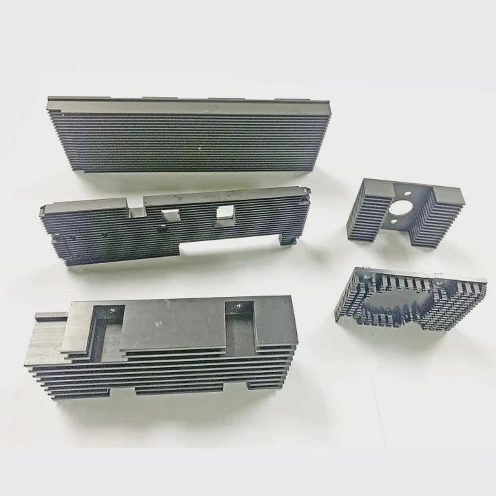
Heat sinks often underperform because of simple design mistakes. Many designs look large but fail to move heat effectively.
Efficiency improves by increasing surface area, reducing thermal resistance, optimizing fin geometry, and improving contact between heat source and sink.
When I look at real projects, the problem is rarely one factor. It is usually a mix of design gaps. A heat sink is not just metal. It is a system of heat flow.
Key methods to improve efficiency
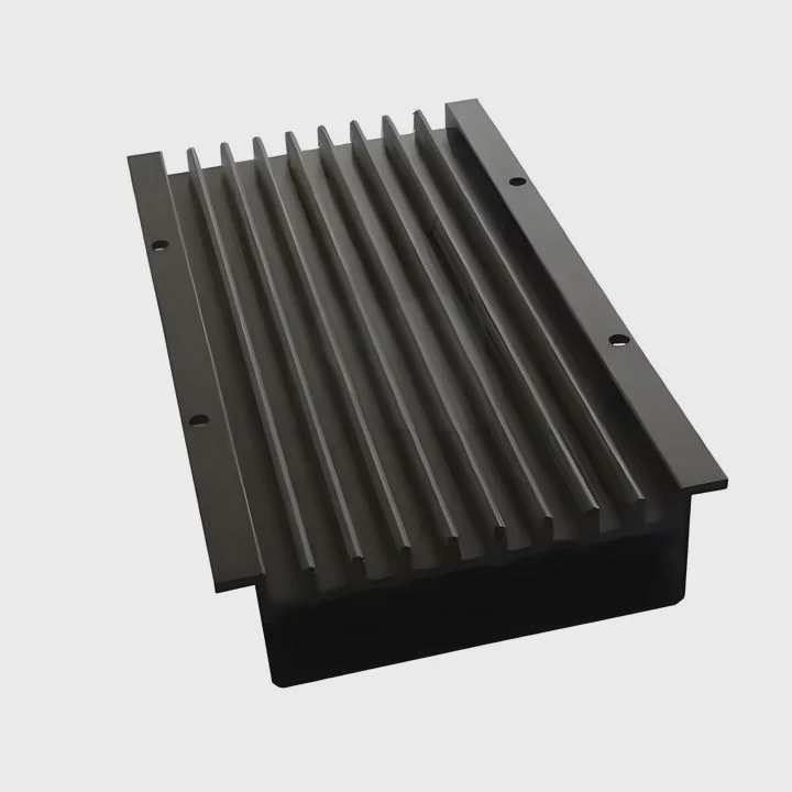
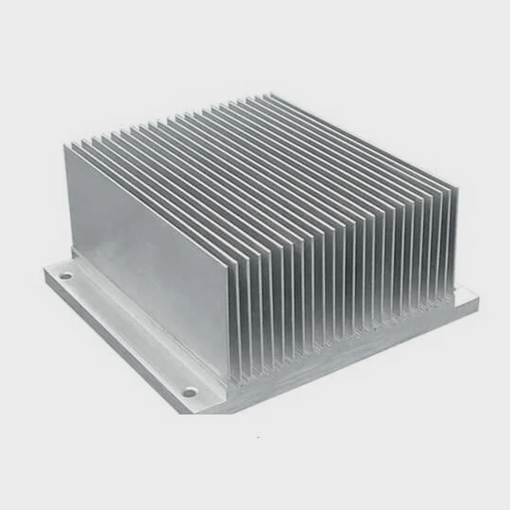
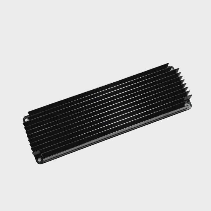
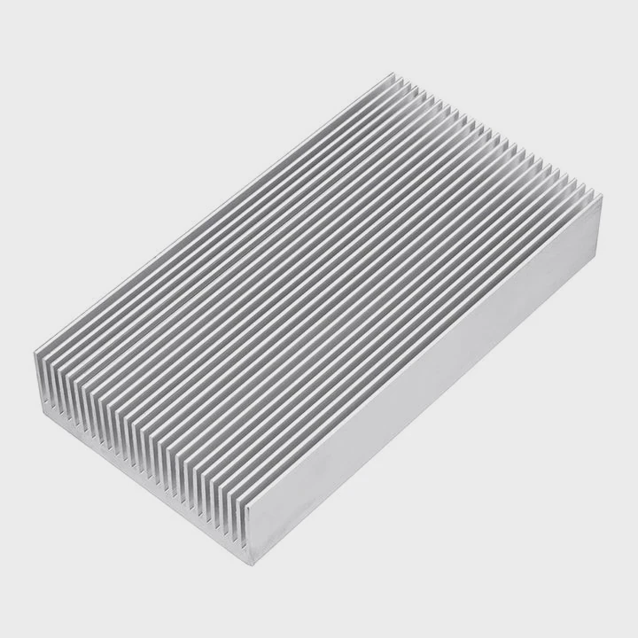
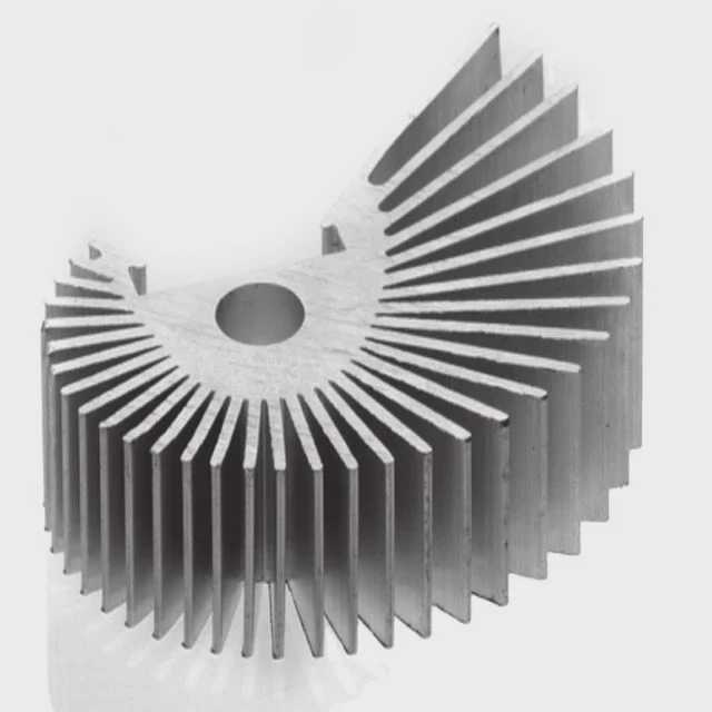
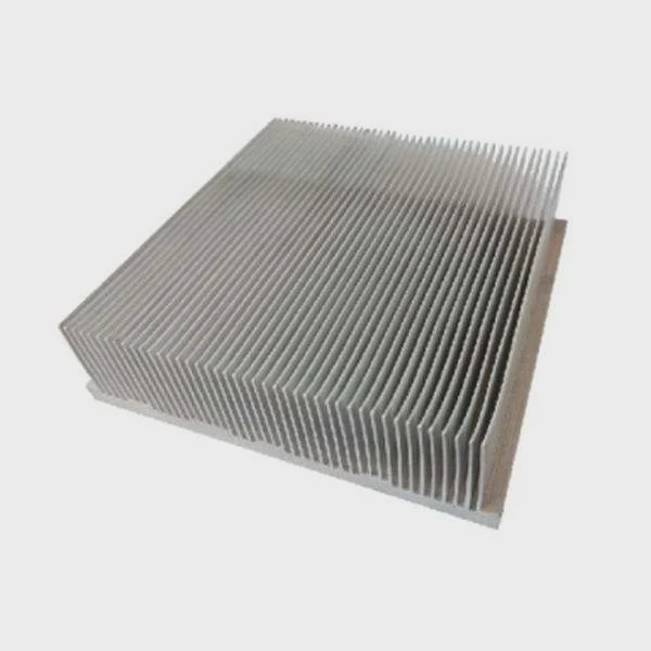
1. Increase surface area
A larger surface allows more heat to transfer to air. This can be done with fins, pins, or folded structures.
- Thin fins increase area but must keep spacing for airflow
- Pin fins work better in multi-direction airflow
2. Reduce thermal resistance
Thermal resistance blocks heat flow. Lower resistance means better efficiency.
| Factor | Impact on Efficiency | Solution |
|---|---|---|
| Interface gap | High resistance | Use thermal paste or pads |
| Poor contact | Uneven heat flow | Improve flatness |
| Long heat path | Slower transfer | Shorten conduction path |
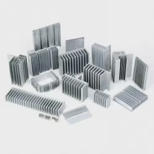
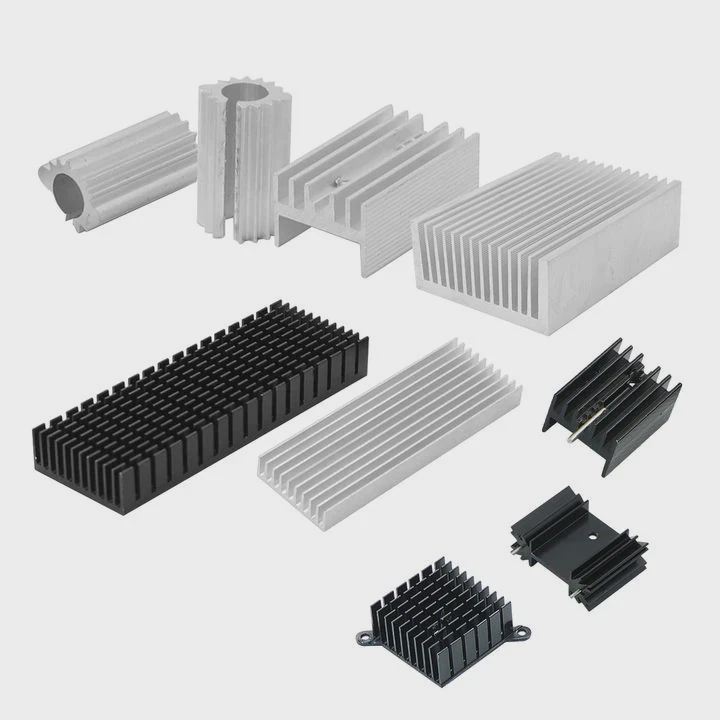
3. Optimize fin design
Fin shape matters more than many expect.
- Straight fins: simple, low cost
- Skived fins: high density, better performance
- Louvered fins: improve turbulence
4. Improve base design
The base spreads heat before fins release it.
- Thicker base improves spreading
- Vapor chamber spreads heat faster
Design balance is critical
More fins do not always mean better cooling. If fins are too close, airflow drops. If fins are too thick, surface area reduces.
A balanced design considers:
- Air velocity
- Heat load
- Space constraints
In many projects, redesigning fin spacing improved efficiency more than increasing size. That is a simple but powerful insight.
Why does airflow improve efficiency?
Many systems fail because airflow is ignored. Even the best heat sink cannot work without proper air movement.
Airflow improves efficiency by removing heated air, increasing heat transfer rate, and maintaining a temperature gradient between the heat sink and environment.
Heat transfer depends on temperature difference. When air stays still, it heats up and reduces this difference. That slows cooling.
How airflow works
Heat moves in three ways:
- Conduction (inside the heat sink)
- Convection (to air)
- Radiation (minor effect here)
Airflow mainly affects convection.
Natural vs forced airflow
| Type | Description | Efficiency |
|---|---|---|
| Natural convection | No fan, relies on buoyancy | Low |
| Forced convection | Uses fan or blower | High |
Forced airflow increases heat transfer coefficient. That directly improves performance.
Airflow design factors
1. Air velocity
Higher speed removes heat faster. But too much speed can create noise and energy loss.
2. Air direction
Air must flow along fins, not against them randomly.
- Parallel flow works best for straight fins
- Cross flow suits pin fins
3. Air distribution
Uneven airflow creates hot spots.
Solutions include:
- Ducting
- Shrouds
- Fan placement optimization
Common airflow mistakes
- Fan placed too far from heat sink
- Blocked inlet or outlet
- Recirculation of hot air
I have seen systems where a small duct improved efficiency by over 30%. That shows airflow design is not optional. It is essential.
Where should design changes be applied?
Many engineers focus only on the heat sink itself. That is a narrow view. Heat management is a full system problem.
Design changes should be applied at the heat source, interface, heat sink structure, and system airflow path for best efficiency improvement.
Improvement starts from the chip and ends at the surrounding air. Each step matters.
Key areas for design changes
1. Heat source level
Reduce heat generation if possible.
- Use efficient components
- Optimize power usage
2. Interface level
This is often ignored but critical.
- Use thermal interface materials (TIM)
- Ensure flat surfaces
- Apply proper mounting pressure
3. Heat sink level
Core design improvements happen here.
- Fin geometry
- Base thickness
- Material selection
4. System level
The full system controls final performance.
- Airflow path
- Enclosure design
- Fan selection
Integrated design approach
A heat sink alone cannot solve all problems. For example:
- A perfect heat sink fails in a closed box
- Strong airflow fails with poor contact
Design workflow
- Define heat load
- Choose material
- Design geometry
- Simulate airflow
- Test and optimize
Real-world insight
In one project, changing only the interface reduced temperature by 8°C. No change in heat sink size was needed. That saved cost and space.
This shows that design changes must be applied where the real bottleneck exists.
Which materials enhance efficiency?
Material choice defines how fast heat moves inside the heat sink. Many designs fail because of wrong material selection.
Materials like aluminum, copper, and advanced composites enhance efficiency by offering high thermal conductivity and structural advantages.
Heat must move quickly from source to fins. Material controls this process.
Common materials
1. Aluminum
Most widely used.
- Lightweight
- Low cost
- Good conductivity (~200 W/m·K)
2. Copper
Higher performance option.
- High conductivity (~400 W/m·K)
- Better heat spreading
- Heavier and more expensive
3. Vapor chamber / heat pipe
Advanced solutions.
- Extremely high effective conductivity
- Ideal for high power density
Material comparison
| Material | Thermal Conductivity | Weight | Cost | Use Case |
|---|---|---|---|---|
| Aluminum | Medium | Light | Low | General applications |
| Copper | High | Heavy | High | High-performance systems |
| Vapor chamber | Very high | Medium | High | Compact high heat loads |
Hybrid designs
Many modern heat sinks combine materials:
- Copper base + aluminum fins
- Vapor chamber + fin stack
This approach balances cost and performance.
Surface treatment
Material surface also matters.
- Anodizing improves corrosion resistance
- Black coating increases radiation slightly
Selection strategy
Material choice depends on:
- Heat load
- Weight limit
- Cost target
- Manufacturing process
In many cases, aluminum remains the best balance. But for high-power systems, copper or vapor chambers become necessary.
Conclusion
Heat sink efficiency improves through better design, airflow, materials, and system integration. A balanced approach delivers the best results, not just bigger size.