How to Design a Heat Sink?
- Yongxing
- 11 Mar ,2026
Thermal problems destroy electronics. Devices overheat, performance drops, and system life becomes shorter. Many engineers face this problem when power density keeps rising.
A good heat sink design removes heat from the source and transfers it to the surrounding air efficiently. It requires understanding heat load, material, airflow, fin geometry, and system layout.
Designing a heat sink is not only about adding metal fins. A reliable solution depends on thermal physics, airflow behavior, and practical manufacturing limits. Understanding these factors helps engineers build stable thermal systems.
What factors influence heat sink design?
Thermal failure often begins with poor design choices. Many engineers focus only on size, but ignore heat load, material limits, and system layout.
Several factors control heat sink performance, including heat power, thermal resistance targets, material conductivity, airflow conditions, and mechanical constraints. Each factor affects how efficiently heat moves away from electronic components.
Designing a heat sink begins with a clear understanding of the thermal problem. Every electronic system produces heat. That heat must move away from the device quickly. If the heat stays in the chip or module, the temperature rises and reliability drops.
Heat Power and Thermal Resistance
The first step in heat sink design is calculating the heat load. Engineers must know how many watts of heat the component generates.
The basic thermal path looks like this:
Chip → Interface Material → Heat Sink Base → Fins → Air
Each step adds thermal resistance. The goal is to keep the total resistance low.
A common formula used in early design is:
[ R{th} = \frac{T{max} - T_{ambient}}{Q} ]
Where:
| Parameter | Meaning |
|---|---|
| Tmax | Maximum allowed device temperature |
| Tambient | Ambient air temperature |
| Q | Heat power (W) |
| Rth | Required thermal resistance |
This value helps engineers determine the heat sink size.
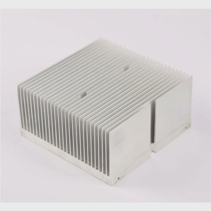
Material Selection
Material strongly affects heat spreading.
Two common materials are aluminum and copper.
| Material | Thermal Conductivity | Weight | Cost | Typical Use |
|---|---|---|---|---|
| Aluminum | ~200 W/m·K | Light | Low | Most heat sinks |
| Copper | ~400 W/m·K | Heavy | Higher | High power systems |
Aluminum works well for most systems. It is light and easy to machine or extrude. Copper spreads heat faster but adds weight and cost.
In many modern designs, engineers combine both materials. Copper spreads heat near the source. Aluminum fins release heat to the air.
Base Thickness and Heat Spreading
The base plate spreads heat from a small chip to a larger fin area.
If the base is too thin, heat concentrates in one region. If the base is too thick, weight increases and thermal resistance may rise.
Engineers often use simulation to balance base thickness.
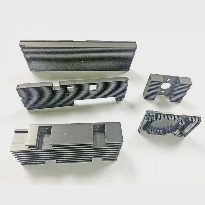
Manufacturing Constraints
Design must also match manufacturing methods.
Common heat sink processes include:
- Aluminum extrusion
- CNC machining
- Vacuum brazing
- Friction stir welding
- Skiving
Each process limits fin height, spacing, and geometry.
A design that ignores manufacturing often fails in production. Good thermal design always considers both performance and manufacturability.
Why is airflow critical for heat sinks?
A heat sink without airflow behaves like a hot metal block. Heat leaves the fins slowly, and temperature continues to rise.
Airflow removes heat from the fins through convection. Higher airflow improves heat transfer and reduces thermal resistance, making airflow one of the most important factors in heat sink performance.
Airflow controls how quickly heat leaves the heat sink. Even a large heat sink performs poorly if air does not move across the fins.
Heat transfer from fins happens mainly through convection.
Natural vs Forced Convection
Two main airflow modes exist.
| Cooling Mode | Description | Typical Applications |
|---|---|---|
| Natural Convection | Air moves due to temperature difference | Passive electronics |
| Forced Convection | Fans push air across fins | Servers, power electronics |
Natural convection relies on hot air rising. This airflow is weak. Heat sinks for passive cooling need large surface area and wide fin spacing.
Forced convection uses fans or blowers. Air velocity increases heat transfer significantly.
Air Velocity and Heat Transfer
Heat transfer coefficient increases with air velocity.
A simplified relationship:
[ Q = h \cdot A \cdot \Delta T ]
Where:
| Parameter | Meaning |
|---|---|
| Q | Heat removed |
| h | Heat transfer coefficient |
| A | Surface area |
| ΔT | Temperature difference |
When airflow increases, the coefficient h increases. This means more heat leaves the fins.
Airflow Direction
Airflow direction also matters.
If airflow moves parallel to the fins, heat removal improves. If airflow hits the fins sideways, turbulence may block airflow channels.
Engineers must design the heat sink based on system airflow.
Typical airflow configurations include:
- Front-to-back airflow (servers)
- Bottom-to-top natural convection
- Cross airflow in compact devices
System-Level Airflow
Many thermal failures happen because engineers design heat sinks without considering the entire system.
Other components may block airflow. Cable routing can disturb air paths. Enclosures trap hot air.
A good design studies the whole thermal system, not just the heat sink.
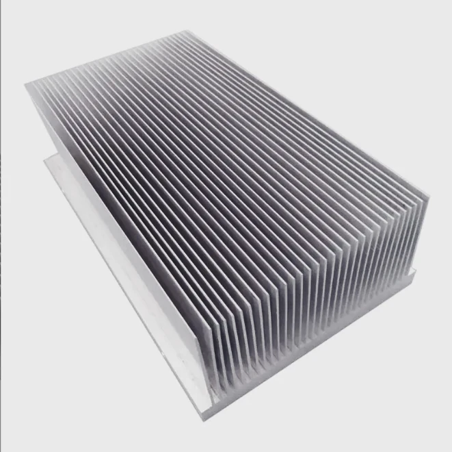
Where should fins be placed for efficiency?
Many beginners believe that more fins always mean better cooling. In reality, poor fin placement can reduce airflow and decrease performance.
Efficient fin placement balances fin height, spacing, and orientation with airflow direction to maximize surface area while allowing air to flow freely through the heat sink.
Fins are the main structures that increase surface area. More surface area allows more heat to transfer into the air. However, fin design must also allow airflow to pass through.
Fin Spacing
If fins are too close together, air cannot flow easily. This creates stagnant air between fins.
If fins are too far apart, the heat sink loses surface area.
Engineers must find the optimal spacing.
Typical spacing guidelines:
| Cooling Type | Recommended Fin Spacing |
|---|---|
| Natural Convection | 6–10 mm |
| Low Airflow | 4–6 mm |
| High Airflow | 2–4 mm |
These numbers change depending on fin height and airflow speed.
Fin Orientation
Fin orientation should match airflow direction.
For example:
- Vertical fins work best in natural convection.
- Parallel fins work best in forced airflow.
If fins block airflow, heat transfer drops significantly.
Fin Height and Aspect Ratio
Tall fins increase surface area. However, airflow weakens along long fins.
Beyond a certain height, extra fin length adds little benefit.
A common design rule uses a balanced aspect ratio.
| Parameter | Typical Range |
|---|---|
| Fin Height | 20–60 mm |
| Fin Thickness | 1–3 mm |
| Fin Spacing | 2–8 mm |
These values depend on manufacturing process and airflow.
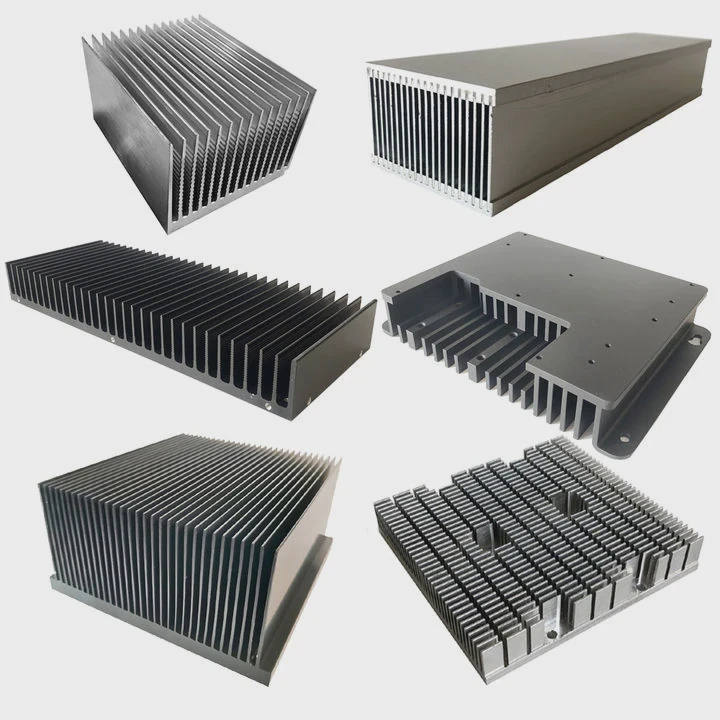
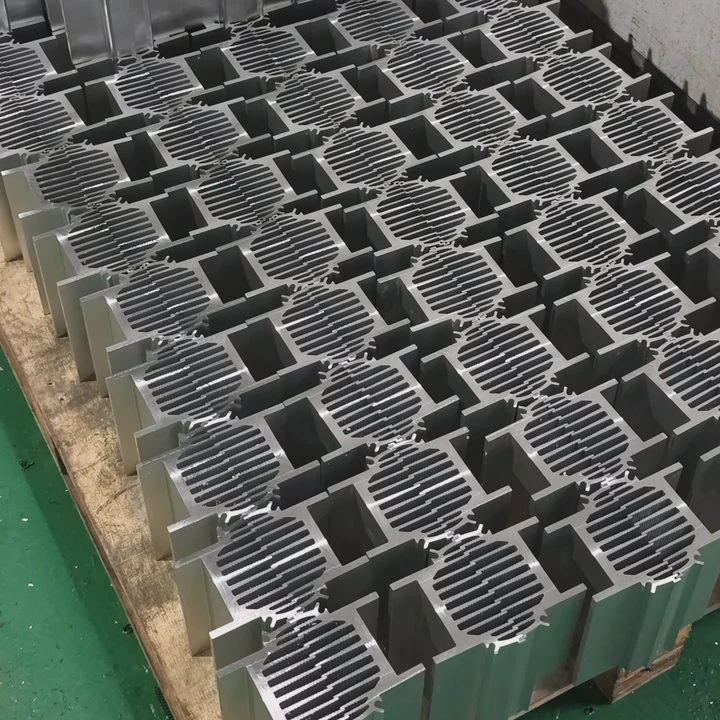
Advanced Fin Structures
Modern heat sinks sometimes use advanced structures:
- Pin fins
- Skived fins
- Folded fins
- Vapor chamber base plates
Pin fins work well when airflow direction is uncertain. Air can move through them from many directions.
Skived fins provide high fin density and excellent thermal performance.
Thermal Spreading Across Fins
Heat must distribute evenly across the base before reaching the fins.
If heat spreads unevenly, only a few fins carry most of the heat load. This reduces efficiency.
Engineers often use heat pipes or vapor chambers to solve this problem.
These devices spread heat across the entire heat sink before airflow removes it.
Which software helps design heat sinks?
Manual calculations help with early design, but modern heat sink design depends heavily on simulation tools.
Thermal simulation software allows engineers to model heat flow, airflow patterns, and temperature distribution before building physical prototypes.
Thermal simulation saves time and cost. Engineers can test multiple design options quickly and find optimal solutions.
Types of Simulation Tools
Heat sink design usually involves three types of software.
| Software Type | Purpose |
|---|---|
| CAD Software | Create 3D models |
| CFD Software | Simulate airflow and heat transfer |
| Thermal Network Tools | Perform quick thermal calculations |
Each tool serves a different role.
Common Thermal Design Software
Several tools are widely used in the electronics industry.
| Software | Main Use |
|---|---|
| ANSYS Icepak | Electronics cooling simulation |
| Siemens Simcenter Flotherm | Detailed thermal analysis |
| SolidWorks Flow Simulation | Integrated CAD thermal simulation |
| COMSOL Multiphysics | Multiphysics modeling |
These tools simulate airflow, temperature fields, and thermal resistance.
What Engineers Simulate
Thermal simulation can analyze many aspects of heat sink performance.
Typical simulation goals include:
- Temperature distribution across the heat sink
- Airflow velocity between fins
- Hot spot detection
- Fan performance and airflow pressure
- Thermal resistance optimization
Simulation results help engineers improve the design before manufacturing prototypes.
Design Iteration
Thermal design is an iterative process.
A typical workflow looks like this:
- Initial thermal calculation
- Heat sink geometry creation
- CFD simulation
- Design adjustment
- Prototype testing
- Final optimization
This process reduces risk and improves reliability.
In real engineering projects, simulation results are often validated with thermal testing. Engineers use thermocouples, infrared cameras, and wind tunnel testing to confirm performance.
Simulation alone is not enough, but it greatly accelerates the design process.
Conclusion
Designing a heat sink requires balancing heat load, airflow, material, and fin geometry. A good design combines thermal physics, airflow understanding, and simulation tools to remove heat efficiently and protect electronic systems.