What Does a Heat Sink Look Like?
- Yongxing
- 13 Mar ,2026
Electronic devices keep getting smaller and more powerful. Heat builds fast. Many engineers see overheating problems but still wonder what a heat sink really looks like.
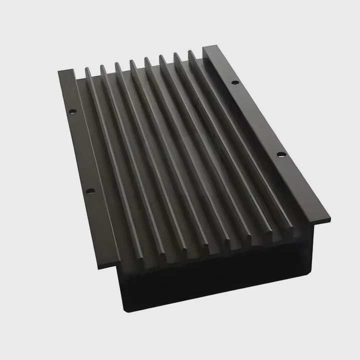
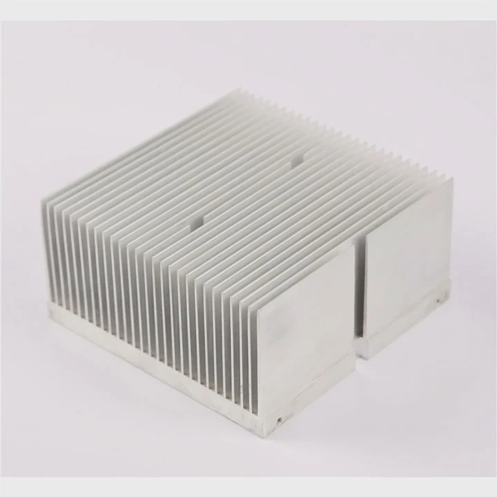
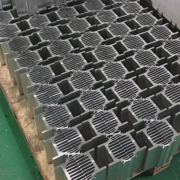
A heat sink usually looks like a metal block with many thin fins attached to a flat base. The fins increase surface area so heat can move into the air quickly. Most heat sinks are made from aluminum and appear as layered, comb-like, or tower-shaped metal structures.
Heat sinks appear simple at first. Yet their structure follows strict thermal design rules. The base spreads heat. The fins move heat into air. Airflow removes the heat. Understanding this structure helps engineers design reliable cooling systems.
How are fins arranged on heat sinks?
Small devices often fail because heat cannot escape fast enough. Many people see fins on heat sinks but do not know why they are arranged in certain patterns.
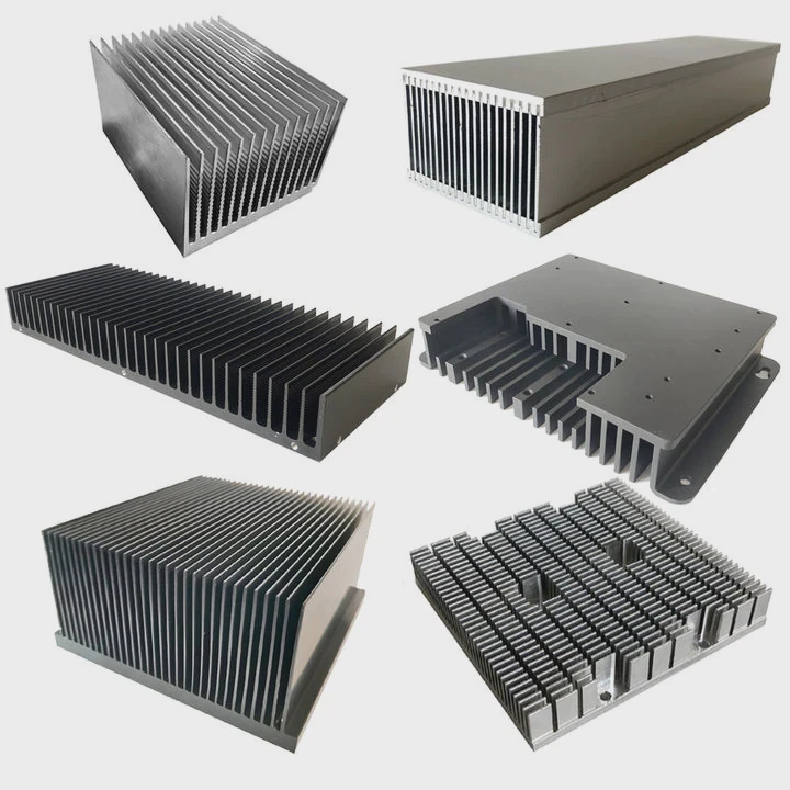
Fins on heat sinks are arranged in parallel, radial, or pin structures. These layouts increase surface area and guide airflow so heat transfers from the base into surrounding air efficiently.
Heat sink fins are not random shapes. Engineers design their layout carefully to control heat flow and airflow. The arrangement affects cooling efficiency, pressure drop, and manufacturing cost.
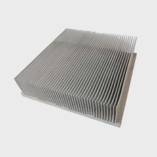
Parallel Plate Fins
Parallel fins are the most common structure. Many aluminum heat sinks use this design because it is simple and effective.
These fins run in straight lines from the base. Air flows between the channels formed by the fins.
Advantages of parallel fins include:
- Large heat transfer surface
- Easy manufacturing with extrusion
- Good airflow direction control
However, spacing between fins must be carefully designed. If fins are too close, airflow becomes restricted.
| Parameter | Typical Range | Purpose |
|---|---|---|
| Fin thickness | 0.8–3 mm | Mechanical strength |
| Fin spacing | 2–10 mm | Allow airflow |
| Fin height | 10–80 mm | Increase surface area |
Parallel fins are common in:
- Power electronics
- Industrial controllers
- LED lighting modules
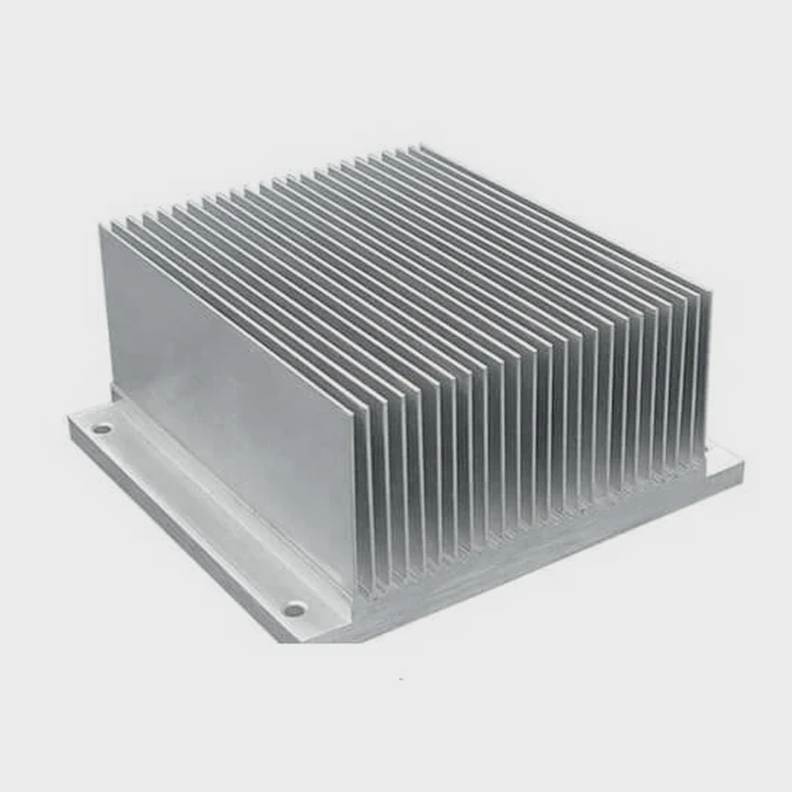
Pin Fin Structures
Pin fin heat sinks use many small pins instead of plates. These pins may be round, square, or elliptical.
Air can flow around the pins in multiple directions. This structure works well when airflow direction is uncertain.
Key advantages include:
- Better performance in turbulent airflow
- Effective natural convection
- Improved heat dissipation in compact spaces
Pin fins are common in:
- CPUs
- GPUs
- telecom base stations
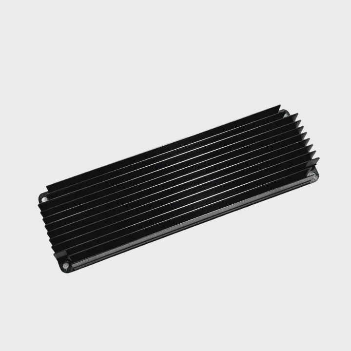
Radial Fin Designs
Radial fins spread outward from the center like spokes on a wheel.
This layout works well with round fans. Air moves outward evenly in all directions.
Radial heat sinks are often used for:
- LED spotlights
- small motors
- circular electronic modules
Each fin layout solves a different cooling problem. Engineers choose the structure based on airflow, power density, and device shape.
Why do most heat sinks use aluminum fins?
Many people assume copper should be the best material for heat sinks. Copper conducts heat better. Yet most heat sinks still use aluminum fins.
Most heat sinks use aluminum fins because aluminum balances thermal conductivity, weight, cost, and manufacturing efficiency. It offers good heat transfer while remaining lightweight and easy to extrude into complex fin structures.
Material choice plays a major role in thermal design. Engineers must consider several factors, not just thermal conductivity.
Thermal Conductivity vs Practical Performance
Copper has higher thermal conductivity than aluminum. However, the difference does not always create better system cooling.
| Material | Thermal Conductivity (W/m·K) | Density | Cost |
|---|---|---|---|
| Copper | ~400 | Heavy | High |
| Aluminum | ~200 | Light | Lower |
Copper spreads heat faster inside the base. Yet fins mainly transfer heat to air. At this stage, surface area matters more than conductivity.
Therefore aluminum performs very well in fin structures.
Manufacturing Advantages
Aluminum allows many cost-effective production methods.
Common processes include:
- aluminum extrusion
- skiving
- stamping
- die casting
- CNC machining
Extrusion is especially important. It can produce long profiles with many fins in a single step.
This method enables:
- thin fins
- consistent spacing
- large production volume
Copper cannot be extruded easily into complex fin shapes. Manufacturing cost becomes much higher.
Weight and Structural Benefits
Weight matters in many systems such as:
- electric vehicles
- communication equipment
- aerospace electronics
Aluminum weighs about one third of copper. Large copper heat sinks would increase system weight significantly.
This is why many high-performance heat sinks use hybrid structures:
| Structure | Purpose |
|---|---|
| Copper base | Fast heat spreading |
| Aluminum fins | Lightweight heat dissipation |
This combination offers strong thermal performance with reasonable cost.
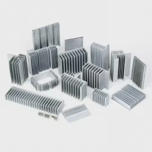
Where can you see heat sink structures?
Heat sinks appear everywhere once you know what they look like. Many people use them daily but rarely notice them.
Heat sink structures appear inside computers, power electronics, LED lights, communication equipment, and electric vehicles. They are usually hidden metal fin components attached to heat-generating chips or modules.
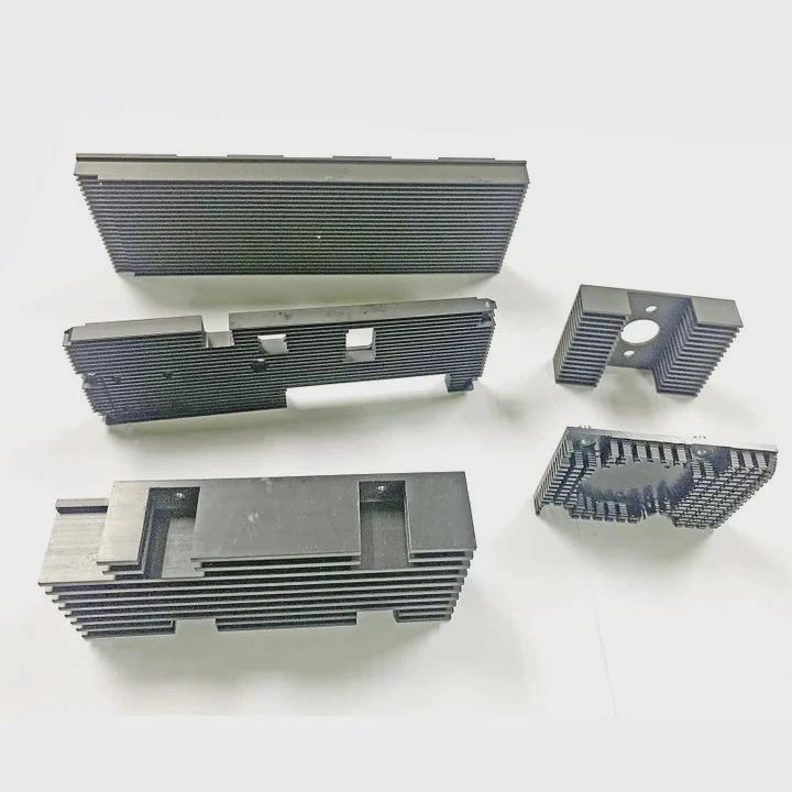
Heat sinks are a fundamental part of modern electronics. Almost every device that consumes power must remove heat.
Consumer Electronics
Many everyday devices use heat sinks.
Common examples include:
- desktop computers
- laptops
- gaming consoles
- routers
- televisions
Inside a computer, the CPU heat sink is one of the most recognizable cooling components. It usually sits under a fan.
This structure forms a cooling system consisting of:
- processor
- thermal interface material
- heat sink
- cooling fan
Industrial Equipment
Industrial electronics generate much higher power than consumer devices.
Examples include:
| Equipment | Heat Source |
|---|---|
| Motor drives | IGBT modules |
| Power supplies | MOSFET switching circuits |
| Inverters | high power semiconductor modules |
These systems require larger heat sinks. Some use liquid cooling plates instead of air cooling.
Communication and 5G Systems
Telecom equipment operates continuously and generates heavy heat loads.
Typical heat sink applications include:
- base station power amplifiers
- signal processing modules
- communication power systems
These systems often combine:
- vapor chamber heat spreaders
- aluminum fin heat sinks
- forced air cooling
Electric Vehicles and Energy Systems
New energy technology requires advanced thermal control.
Heat sinks appear in:
- battery management systems
- onboard chargers
- traction inverters
- energy storage converters
In high power applications, liquid cooling heat sinks are becoming more common.
Understanding where heat sinks appear helps engineers recognize how critical thermal design is across industries.
Which designs improve airflow around heat sinks?
Even the best heat sink cannot work well without airflow. Poor airflow traps hot air around fins and reduces cooling efficiency.
Heat sink designs improve airflow by optimizing fin spacing, fin shape, orientation, and airflow channels. Structures such as pin fins, staggered fins, and ducted cooling paths help air move smoothly through the heat sink.
Airflow design is a critical part of thermal engineering. A heat sink must allow air to carry heat away continuously.
Fin Spacing Optimization
Fin spacing controls how easily air can move through the heat sink.
If spacing is too small:
- airflow resistance increases
- hot air becomes trapped
- cooling performance drops
If spacing is too large:
- surface area decreases
- heat transfer becomes weaker
Engineers calculate spacing based on airflow conditions.
| Cooling Mode | Recommended Fin Gap |
|---|---|
| Natural convection | 6–12 mm |
| Forced air cooling | 2–6 mm |
Natural convection systems require larger gaps because airflow is weaker.
Staggered Fin Layout
Staggered fins improve airflow mixing. Instead of straight channels, the air path becomes slightly disturbed.
Benefits include:
- stronger turbulence
- improved heat transfer
- reduced boundary layer buildup
This design is common in high power cooling systems.
Pin Fin Turbulence
Pin fins allow air to move in multiple directions.
This creates small turbulent zones around each pin.
The effect improves heat transfer because moving air constantly replaces warm air near the surface.
Pin fins work well when:
- airflow direction changes
- space is limited
- fan position varies
Air Duct and Fan Integration
Heat sink design often includes airflow channels.
Engineers combine heat sinks with:
- axial fans
- blower fans
- duct systems
The goal is simple: move cool air through fins and remove hot air quickly.
Many high power systems use airflow guides to ensure air passes directly through heat sink channels instead of bypassing them.
This integrated approach greatly improves thermal efficiency.
Conclusion
A heat sink looks simple, but its design reflects deep thermal engineering. The base spreads heat, fins expand surface area, and airflow removes heat. Understanding fin layout, materials, applications, and airflow design helps engineers build reliable cooling solutions.