What Is the Maximum Thermal Capacity of a Heat Sink?
- Yongxing
- 08 Jul ,2026
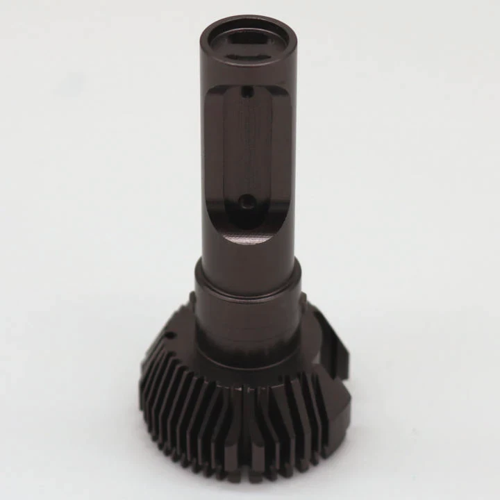
Electronic systems continue to become smaller and more powerful. At the same time, heat generation keeps increasing. Many engineers and buyers struggle to determine how much heat a heat sink can actually remove before temperatures reach unsafe levels.
The maximum thermal capacity of a heat sink depends on its thermal resistance, material properties, surface area, fin geometry, airflow conditions, and allowable temperature rise. A heat sink can dissipate anywhere from a few watts to several kilowatts when these factors are properly optimized.
Many people assume that a larger heat sink automatically provides higher cooling performance. Size matters, but it is only one part of the equation. Material selection, airflow management, fin structure, and system design often have a greater impact on real-world thermal performance. Understanding these factors helps engineers choose the right thermal solution and avoid overheating problems during operation.
A heat sink should never be evaluated as a standalone component. It works as part of a complete thermal management system. The heat source, thermal interface materials, airflow path, mounting method, and environmental conditions all affect the final thermal capacity. By understanding how these elements interact, it becomes easier to estimate realistic heat dissipation limits and select the most suitable cooling solution.
How to Calculate Heat Dissipation Limits?
Heat-related failures often occur because thermal calculations are overlooked during the early design stage. Once a product enters production, fixing thermal problems becomes expensive and time-consuming.
Heat dissipation limits are calculated by dividing the allowable temperature rise by the total thermal resistance of the system. This calculation provides the maximum amount of heat that can be safely removed while maintaining acceptable operating temperatures.

The thermal capacity of a heat sink is not a fixed number. It changes according to environmental conditions, airflow, mounting quality, and system requirements. A proper calculation begins with understanding the maximum operating temperature of the electronic component and the expected ambient temperature.
Understanding the Basic Formula
The most common thermal calculation uses the following equation:
Heat Load (W) = Temperature Difference (°C) ÷ Thermal Resistance (°C/W)
The temperature difference is the allowable rise above ambient temperature. Thermal resistance represents how effectively heat travels from the device into the surrounding air.
Consider the following example:
| Parameter | Symbol | Example Value |
|---|---|---|
| Junction Temperature | Tj | 100°C |
| Ambient Temperature | Ta | 40°C |
| Thermal Resistance | Rθ | 0.5°C/W |
| Maximum Heat Load | Q | 120W |
Calculation:
Q = (100 - 40) ÷ 0.5
Q = 120W
This result indicates that the cooling system can theoretically dissipate 120 watts while maintaining the target temperature.
Why Thermal Resistance Is Important
Thermal resistance is one of the most important measurements in heat sink design. Lower thermal resistance allows heat to move more easily through the cooling system.
Several factors influence thermal resistance:
- Material conductivity
- Surface area
- Fin structure
- Airflow speed
- Thermal interface quality
- Contact pressure
A small reduction in thermal resistance can create a noticeable improvement in heat dissipation capability.
Real Operating Conditions
Many thermal calculations assume ideal laboratory conditions. Real environments are usually less forgiving.
Several factors can reduce actual performance:
| Operating Condition | Impact on Cooling |
|---|---|
| Dust accumulation | Reduces airflow |
| High ambient temperature | Decreases cooling margin |
| Poor mounting pressure | Increases thermal resistance |
| Blocked airflow path | Lowers heat transfer efficiency |
| Thermal interface degradation | Raises operating temperature |
A project may pass simulation testing but still experience thermal issues after installation. This is why thermal validation remains essential during product development.
The Importance of Safety Margins
Experienced thermal engineers rarely design a system to operate exactly at its theoretical limit.
A safety margin helps compensate for:
- Manufacturing tolerances
- Fan aging
- Environmental changes
- Unexpected operating conditions
- Future product upgrades
For example, a cooling solution capable of dissipating 100W may be selected for a device generating only 75W. This approach improves long-term reliability and reduces the risk of thermal failure.
Looking Beyond the Numbers
Thermal calculations provide a useful starting point, but they should never replace testing. Every system behaves differently once assembled. Component placement, airflow restrictions, and enclosure design can all influence results.
In many industrial applications, actual thermal performance differs from calculated values. For this reason, thermal simulations and physical testing should always work together. Accurate calculations establish expectations, while testing confirms real-world performance.
Do Material Types Affect Capacity?
Many buyers compare heat sinks based on size alone. In reality, two heat sinks with identical dimensions can perform very differently because of material selection.
Yes, material type directly affects thermal capacity because thermal conductivity determines how quickly heat moves through the heat sink and spreads across the available cooling surface.
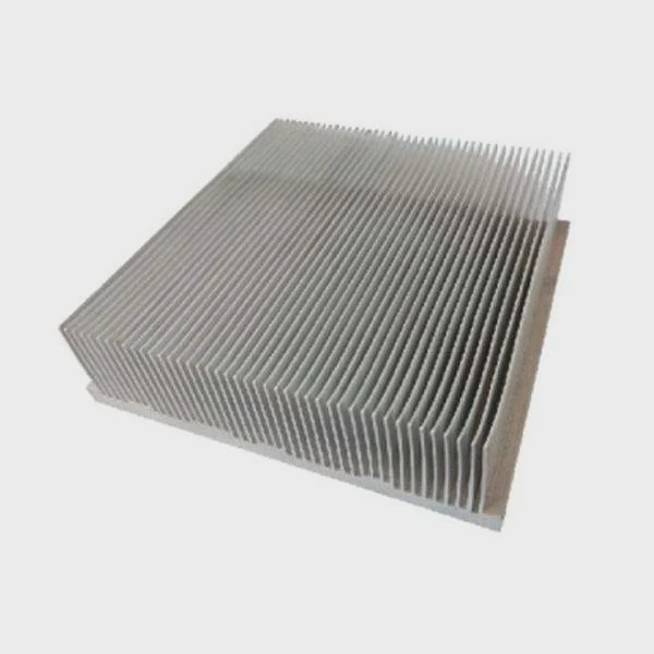
Material selection plays a major role in thermal management. Different materials offer different balances of conductivity, weight, cost, manufacturability, and durability.
Common Heat Sink Materials
The most frequently used heat sink materials include aluminum, copper, graphite, and advanced phase-change structures.
| Material | Thermal Conductivity (W/m·K) | Main Advantage |
|---|---|---|
| Aluminum 6063 | ~200 | Lightweight and economical |
| Copper | ~390 | Excellent heat transfer |
| Graphite | 300-1500+ | High directional conductivity |
| Vapor Chamber Structure | Equivalent >5000 | Outstanding heat spreading |
Copper transfers heat almost twice as effectively as aluminum. However, conductivity is only one factor that influences performance.
Aluminum Versus Copper
Aluminum remains the most widely used heat sink material in many industries.
Advantages of aluminum include:
- Lower weight
- Lower cost
- Easy extrusion processing
- Good corrosion resistance
- Suitable for high-volume production
Copper offers different benefits:
- Higher conductivity
- Better hotspot management
- Faster heat spreading
- Improved thermal uniformity
The choice often depends on the application requirements.
Material Selection in Different Industries
Different industries prioritize different performance goals.
| Industry | Material Preference |
|---|---|
| Telecommunications | Lightweight aluminum |
| Data Centers | High-performance copper solutions |
| Rail Transit | Reliable hybrid structures |
| Medical Equipment | Stable precision cooling |
| Energy Storage Systems | High-capacity thermal management |
A thermal solution that works well for a communication device may not be suitable for a high-power inverter or rail transportation system.
Hybrid Material Designs
Modern thermal management systems increasingly combine multiple materials.
Common examples include:
- Copper base with aluminum fins
- Heat pipe integrated heat sinks
- Vapor chamber assemblies
- Phase-change thermal modules
These structures attempt to combine the strengths of different materials while minimizing their weaknesses.
Manufacturing Also Matters
Material performance depends heavily on manufacturing quality.
Several production methods influence thermal performance:
Vacuum Brazing
Vacuum brazing creates strong thermal joints with low resistance. This process is widely used in high-power cooling systems.
Friction Stir Welding
Friction stir welding creates reliable aluminum structures while maintaining excellent thermal performance.
Laser Welding
Laser welding provides precise joining and supports complex thermal assemblies.
Diffusion Bonding
Diffusion bonding produces extremely strong interfaces with excellent thermal conductivity.
Material selection should never be made based solely on conductivity values. Weight restrictions, mechanical requirements, cost targets, and production volumes all affect the final decision. A well-designed aluminum heat sink can often outperform a poorly designed copper heat sink. The most successful thermal solutions balance conductivity, geometry, airflow, manufacturing quality, and overall system requirements.
Are Fin Designs Critical for High Loads?
Many engineers focus on materials when trying to improve cooling performance. In many cases, fin geometry has an even greater effect on heat dissipation.
Yes, fin design is critical because fins create the surface area that transfers heat into the surrounding environment. Proper fin geometry can significantly increase thermal capacity without greatly increasing weight or size.
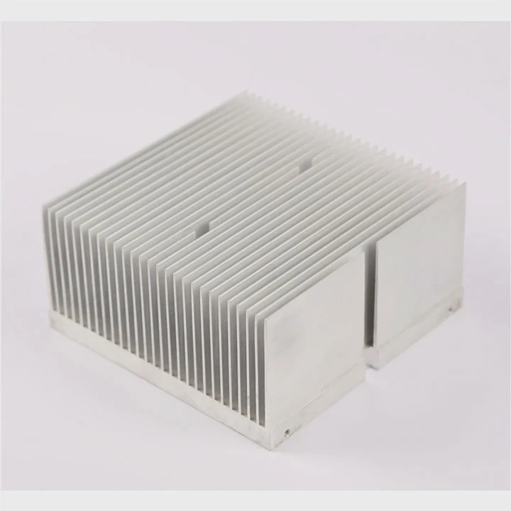
The primary purpose of fins is to maximize the contact area between the heat sink and the cooling medium. More effective surface area generally means better heat transfer.
Why Surface Area Matters
Heat moves from the heat sink surface into the surrounding air.
Increasing surface area provides:
- More heat transfer opportunities
- Lower thermal resistance
- Improved cooling efficiency
- Better temperature control
However, simply adding more fins does not always improve performance.
Fin Spacing Is Important
Fin spacing directly affects airflow behavior.
When fins are too close together:
- Airflow becomes restricted
- Pressure drop increases
- Cooling efficiency decreases
When fins are too far apart:
- Surface area is reduced
- Material utilization drops
- Cooling potential decreases
The best design balances airflow and surface area.
Common Fin Types
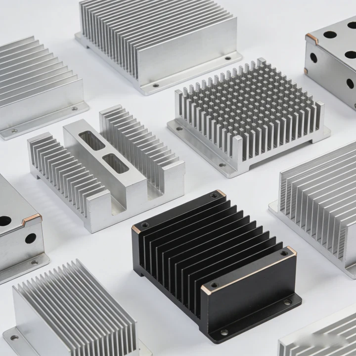
Several fin structures are commonly used in thermal management.
| Fin Type | Advantages | Typical Applications |
|---|---|---|
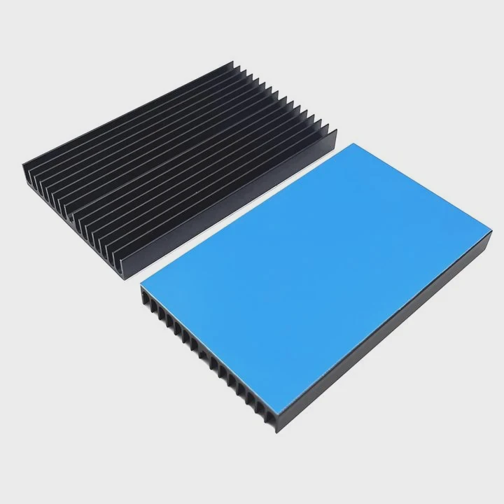
| Straight Fin | Low cost and simple production | Industrial equipment |
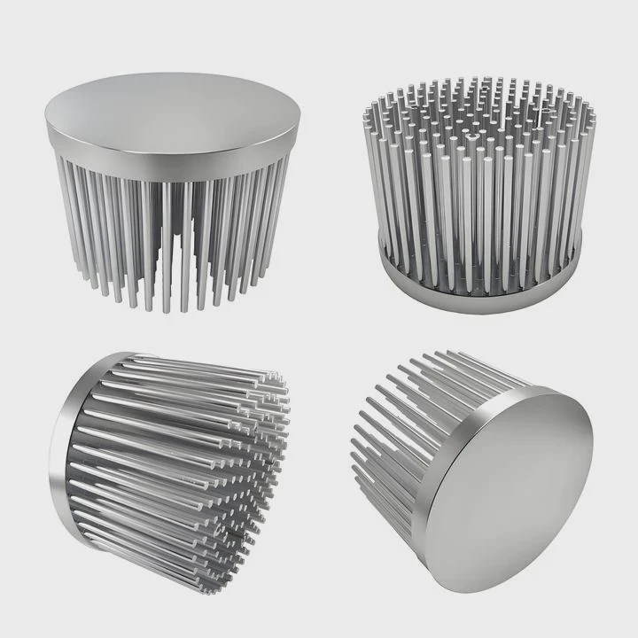
| Pin Fin | Supports multidirectional airflow | Telecom systems |
| Skived Fin | High fin density | Power electronics |
| Folded Fin | Lightweight structure | Compact systems |
| Extruded Fin | Economical manufacturing | General cooling applications |
Each fin type creates different airflow patterns and thermal behavior.
Airflow and Fin Interaction
Fin performance depends heavily on airflow conditions.
Natural convection systems generally require:
- Wider spacing
- Lower airflow resistance
- Vertical fin orientation
Forced-air systems can support:
- Higher fin density
- Increased surface area
- More aggressive geometries
Computational Fluid Dynamics (CFD) is often used to analyze airflow performance before manufacturing begins.
Fin Optimization for High-Power Systems
As heat loads increase, fin design becomes even more important.
Thermal engineers typically optimize:
- Fin height
- Fin thickness
- Fin spacing
- Fin orientation
- Airflow direction
These adjustments can significantly improve thermal performance without increasing the overall footprint.
Real-World Example
A high-power industrial controller experienced excessive temperatures during testing. The original design used a conventional extruded heat sink. Instead of increasing the heat sink size, engineers redesigned the fin structure to improve airflow penetration.
The new design produced:
- Lower thermal resistance
- Better airflow distribution
- Reduced hotspot temperatures
- Improved overall efficiency
The enclosure dimensions remained unchanged, yet thermal performance improved significantly.
This example highlights an important lesson. Cooling performance is often limited by airflow management rather than material volume alone.
For high-load applications, fin geometry directly influences heat transfer efficiency, pressure drop, manufacturing cost, and overall thermal capacity. A carefully optimized fin design can often deliver greater improvements than simply increasing the size or weight of the heat sink.
Can Active Cooling Extend Thermal Capacity?
Every passive cooling system eventually reaches its limit. As power levels continue to increase, engineers often need additional cooling methods to maintain safe operating temperatures.
Active cooling extends thermal capacity by increasing heat transfer through forced airflow, liquid circulation, heat pipes, or phase-change technologies. These methods can dramatically increase heat dissipation compared with passive cooling alone.
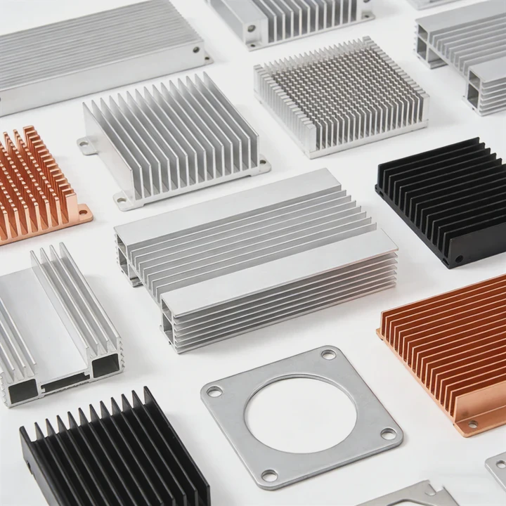
Passive heat sinks rely entirely on natural convection. Active cooling introduces additional energy to improve heat transfer efficiency.
Common Active Cooling Methods
| Cooling Technology | Typical Improvement |
|---|---|
| Axial Fan | 2x to 5x |
| Blower System | 3x to 8x |
| Heat Pipe Assisted Cooling | Significant hotspot reduction |
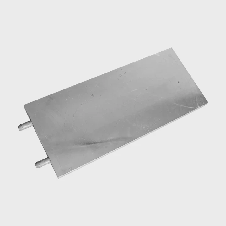
| Liquid Cooling Plate | Very high heat removal |
| Two-Phase Cooling | Extreme thermal performance |
Actual results depend on system design and operating conditions.
Forced Air Cooling
Fans remain one of the most common active cooling solutions.
Key benefits include:
- Lower thermal resistance
- Compact implementation
- Relatively low cost
- Easy integration
Potential drawbacks include:
- Noise generation
- Dust accumulation
- Mechanical wear
- Maintenance requirements
Fan reliability becomes especially important in industrial environments.
Heat Pipes and Vapor Chambers
Heat pipes and vapor chambers improve heat spreading efficiency.
These technologies help by:
- Moving heat rapidly
- Reducing hotspot formation
- Improving temperature uniformity
- Supporting compact layouts
They are particularly useful when heat is generated in a small area.
Liquid Cooling Systems
As power density increases, liquid cooling becomes increasingly attractive.
Advantages include:
- Higher heat transfer coefficients
- Compact thermal structures
- Better temperature consistency
- Greater heat removal capability
Typical applications include:
- Energy storage systems
- Electric vehicles
- Data centers
- Industrial laser equipment
- High-power electronics
Choosing the Right Cooling Strategy
The best cooling solution depends on application requirements.
| Design Factor | Passive Cooling | Active Air Cooling | Liquid Cooling |
|---|---|---|---|
| Cost | Low | Medium | Higher |
| Maintenance | Minimal | Moderate | Moderate |
| Heat Capacity | Low to Medium | Medium to High | High |
| Complexity | Low | Medium | High |
| Space Efficiency | Medium | High | Very High |
Each approach offers different advantages and trade-offs.
Combining Multiple Technologies
The highest-performing thermal systems rarely depend on a single cooling method.
Many advanced solutions combine:
- Vapor chambers
- Heat pipes
- Aluminum heat sinks
- Copper heat spreaders
- Forced-air cooling
- Liquid cooling plates
By combining these technologies, engineers can handle heat loads that would be impossible for a passive heat sink alone.
A modern thermal management system should always be evaluated as a complete solution rather than a collection of separate components. The interaction between heat spreading, airflow management, material selection, and cooling technology ultimately determines the maximum thermal capacity.
Conclusion
The maximum thermal capacity of a heat sink depends on thermal resistance, material selection, fin design, airflow conditions, and cooling technology. Accurate calculations, optimized structures, and proper thermal management strategies allow heat sinks to dissipate heat efficiently while maintaining safe operating temperatures in demanding applications.