Which Heat Sinks Are Suitable for LED Cooling?
- Yongxing
- 26 Jun ,2026
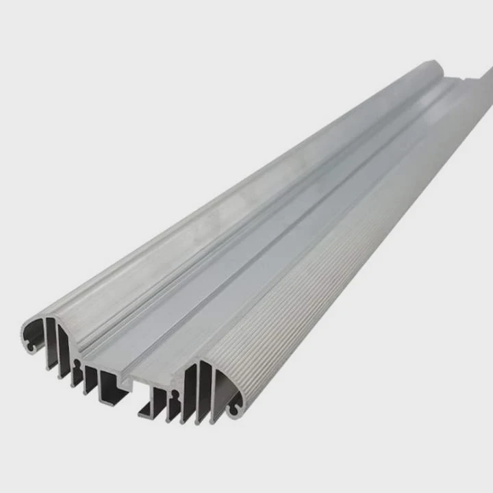
Many LED systems lose brightness or fail early because of poor heat control. A strong LED chip alone cannot guarantee long service life if heat stays trapped inside the product.
The most suitable heat sinks for LED cooling depend on LED power, airflow conditions, thermal resistance targets, and installation space. Aluminum heat sinks are widely used, while vapor chambers, heat pipes, and fan-assisted systems work better for high-power or compact LED applications.
Thermal management has become one of the most important parts of modern LED product design. High-power LEDs now operate in smaller spaces and under harsher environments. This creates more heat concentration than many engineers expect. Good thermal control improves not only LED lifespan but also brightness stability, energy efficiency, and product reliability. That is why selecting the right heat sink is now part of the full product engineering process.
Do LED Applications Need High-Efficiency Heat Sinks?
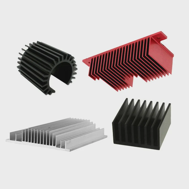
Many people believe LEDs generate very little heat. This is only partly true. LEDs are more efficient than traditional lighting, but they still convert a large amount of electrical energy into heat.
Yes, many LED applications need high-efficiency heat sinks because LED junction temperature strongly affects brightness, efficiency, color stability, and service life. Better cooling helps LEDs operate more safely and consistently over time.
Modern LED systems are becoming smaller while producing more power. This trend increases thermal density inside the product. If heat cannot leave the LED junction quickly enough, performance begins to decline.
Why LED Heat Matters
Excess heat creates several problems inside LED systems:
| Thermal Issue | Effect on LED Performance |
|---|---|
| High junction temperature | Reduced brightness |
| Heat accumulation | Faster aging |
| Uneven temperature | Color variation |
| Thermal cycling | Solder fatigue |
| Long-term overheating | Shorter lifespan |
Many LED failures happen slowly. The product may continue working, but lumen output gradually decreases. Customers often notice lower brightness before complete failure occurs.
Heat Directly Impacts LED Efficiency
LED efficiency decreases as temperature rises. This means more electrical power becomes wasted heat instead of useful light.
In high-power systems, this creates a negative cycle:
- Higher temperature lowers efficiency
- Lower efficiency creates more heat
- More heat raises temperature further
Without effective cooling, the system becomes unstable during long operating periods.
Common Heat Sink Types for LEDs
Different LED applications require different cooling methods.
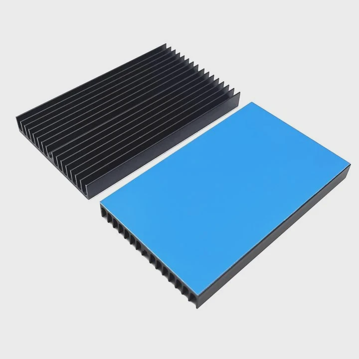
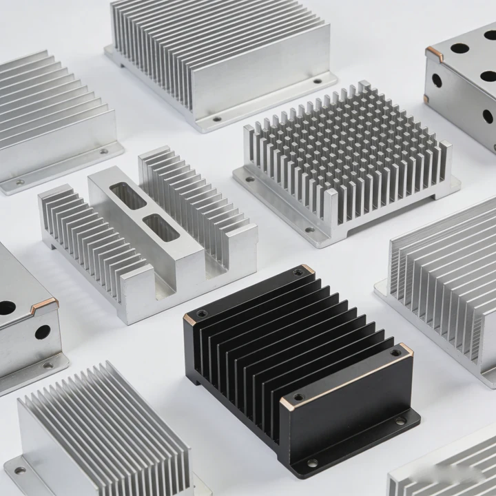
Extruded Aluminum Heat Sinks
Extruded aluminum remains the most common LED cooling solution.
Advantages include:
- Low weight
- Good thermal conductivity
- Easy manufacturing
- Lower production cost
- Flexible fin structures
These heat sinks are widely used in:
- Street lights
- Industrial lighting
- Commercial lighting
- Communication equipment
Copper Heat Sinks
Copper offers higher thermal conductivity than aluminum.
Copper is useful when:
- Heat density is very high
- Space is limited
- Rapid heat spreading is needed
However, copper increases:
- Weight
- Material cost
- Machining complexity
Vapor Chamber Heat Sinks
Vapor chambers spread heat very quickly across the base surface.
These systems work well in:
- Compact LED modules
- Automotive lighting
- Medical devices
- UV curing systems
They help reduce local hot spots around the LED package.
Heat Sink Efficiency Depends on More Than Material
Many engineers focus only on material conductivity. In reality, thermal performance also depends on:
- Fin spacing
- Airflow direction
- Surface area
- Base thickness
- Interface quality
A poorly designed copper heat sink may perform worse than a properly designed aluminum structure.
Long-Term Stability Is the Real Goal
The purpose of LED cooling is not simply reducing temperature during short testing periods. Good thermal design must maintain stable performance over thousands of operating hours.
A stable thermal system protects:
- Brightness consistency
- Driver electronics
- PCB reliability
- Optical components
This is especially important for outdoor and industrial applications where maintenance costs are high.
How to Select Thermal Resistance for LED Cooling?
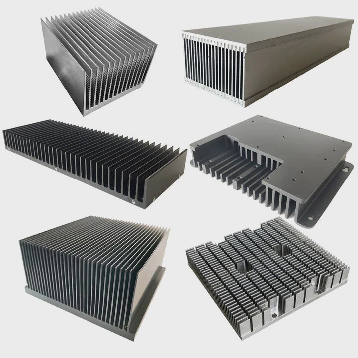
Many LED thermal problems begin with incorrect thermal resistance calculations. A design may work during early testing but fail later in real operating conditions.
Thermal resistance for LED cooling should be selected according to LED power, maximum junction temperature, ambient temperature, airflow conditions, and long-term reliability targets. Lower thermal resistance improves heat transfer and thermal stability.
Thermal resistance controls how easily heat moves from the LED junction into the surrounding environment.
Basic Thermal Resistance Formula
The standard thermal relationship is:
[ R_{th} = \frac{T_j - T_a}{Q} ]
Where:
- (R_{th}) = thermal resistance
- (T_j) = junction temperature
- (T_a) = ambient temperature
- (Q) = heat power
This equation helps engineers determine the maximum allowable thermal resistance for the cooling system.
Ambient Temperature Is Often Underestimated
Many designs use laboratory temperatures during simulation. Real environments are often much hotter.
| Environment | Typical Ambient Temperature |
|---|---|
| Laboratory testing | 25°C |
| Industrial workshop | 40°C |
| Outdoor summer operation | 50°C+ |
| Sealed enclosure | Higher internal temperature |
A heat sink designed only for laboratory conditions may not survive real installation environments.
Junction Temperature Controls Lifespan
LED manufacturers normally specify maximum junction temperature limits. However, operating near those limits reduces long-term reliability.
Typical Thermal Targets
| Junction Temperature | Reliability Level |
|---|---|
| Below 85°C | Excellent |
| 85°C-100°C | Acceptable |
| Above 100°C | Increased degradation risk |
Lower junction temperature usually means longer LED lifespan.
Thermal Interface Resistance Matters
The total thermal path includes more than the heat sink itself.
Additional resistance appears in:
- Thermal grease
- Thermal pads
- PCB layers
- Solder joints
- Mounting surfaces
Poor assembly quality can increase thermal resistance significantly.
In some projects, simulation results appear safe while actual products operate much hotter. This difference often comes from imperfect contact surfaces or uneven mounting pressure.
Fin Design Changes Thermal Resistance
Heat sink fin structure strongly affects airflow and cooling efficiency.
Fin Height
Taller fins increase surface area. However, excessive height may reduce airflow.
Fin Spacing
Very narrow spacing can trap heat if natural airflow becomes restricted.
Base Thickness
A thicker base spreads heat more evenly but increases product weight.
Surface Treatment
Black anodizing slightly improves radiation performance in natural convection systems.
Thermal Safety Margin Is Important
Real manufacturing introduces variation into thermal performance.
Common influences include:
- Material tolerance
- Surface flatness deviation
- Coating thickness
- Welding deformation
- Dust accumulation
Good thermal design always includes additional safety margin beyond simulation values.
Thermal Design Should Match Real Usage
LED products often operate continuously for many hours each day. This creates long-term thermal stress.
Reliable thermal design should consider:
- Seasonal temperature changes
- Installation orientation
- Enclosure restrictions
- Long operating cycles
- Environmental contamination
Thermal resistance is not only a calculation target. It is part of overall product reliability engineering.
Are Fan-Assisted Heat Sinks Needed?

Many LED systems work well with passive cooling. However, compact high-power products sometimes require stronger airflow support.
Fan-assisted heat sinks are needed when passive cooling cannot keep LED junction temperature within safe operating limits. Forced airflow improves convection efficiency and lowers thermal resistance significantly.
Passive cooling remains popular because it is simple and reliable.
Advantages of Passive Cooling
Passive heat sinks offer several benefits:
- No moving parts
- Silent operation
- Lower maintenance
- Higher long-term reliability
- Lower power consumption
These systems are widely used in:
- Outdoor lighting
- Railway systems
- Architectural lighting
- Industrial control cabinets
Compact Products Create Thermal Challenges
Modern products continue shrinking while increasing power output.
This creates several thermal problems:
| Design Limitation | Thermal Effect |
|---|---|
| Smaller enclosure | Reduced airflow |
| Thin structure | Limited fin size |
| High LED density | Local heat concentration |
| Sealed housing | Heat accumulation |
Under these conditions, passive cooling may no longer provide enough thermal performance.
Fans Improve Convection Efficiency
Forced airflow greatly increases heat transfer efficiency.
Benefits include:
- Lower thermal resistance
- Faster heat removal
- Smaller heat sink size
- Improved temperature stability
This becomes important in:
- UV LED systems
- Medical devices
- Stage lighting
- High-power industrial equipment
Smaller Heat Sinks Become Possible
One major advantage of fan-assisted cooling is reduced product size.
Without airflow support, passive heat sinks may become too large or too heavy for compact systems.
Active cooling allows:
- Higher power density
- Reduced aluminum usage
- Smaller enclosure design
- Better thermal control
Fans Also Create Risks
Fans improve cooling but introduce additional failure points.
Common Fan Problems
| Fan Issue | System Impact |
|---|---|
| Dust buildup | Reduced airflow |
| Bearing wear | Mechanical failure |
| Noise generation | User discomfort |
| Power usage | Higher system consumption |
Because of these risks, passive cooling is still preferred whenever possible.
Hybrid Cooling Systems Are Increasing
Many advanced LED systems now combine several cooling methods together.
Examples include:
- Vapor chamber + fins
- Heat pipes + airflow
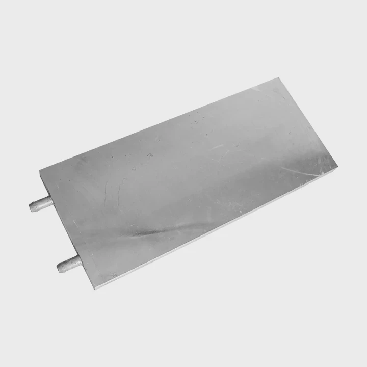
- Liquid cooling + radiator
- Copper base + aluminum fins
Hybrid systems help balance thermal performance, size, and cost.
Smart Fan Control Improves Reliability
Modern LED products increasingly use temperature-controlled fan systems.
Advantages include:
- Lower noise
- Reduced energy use
- Longer fan lifespan
- Stable operating temperature
Variable-speed cooling is often more efficient than constant maximum airflow.
Cooling Choice Depends on Application
The correct cooling method depends on several factors:
- Power level
- Product size
- Environmental conditions
- Maintenance expectations
- Noise requirements
There is no universal solution for every LED system.
What Design Features Improve LED Lifespan?
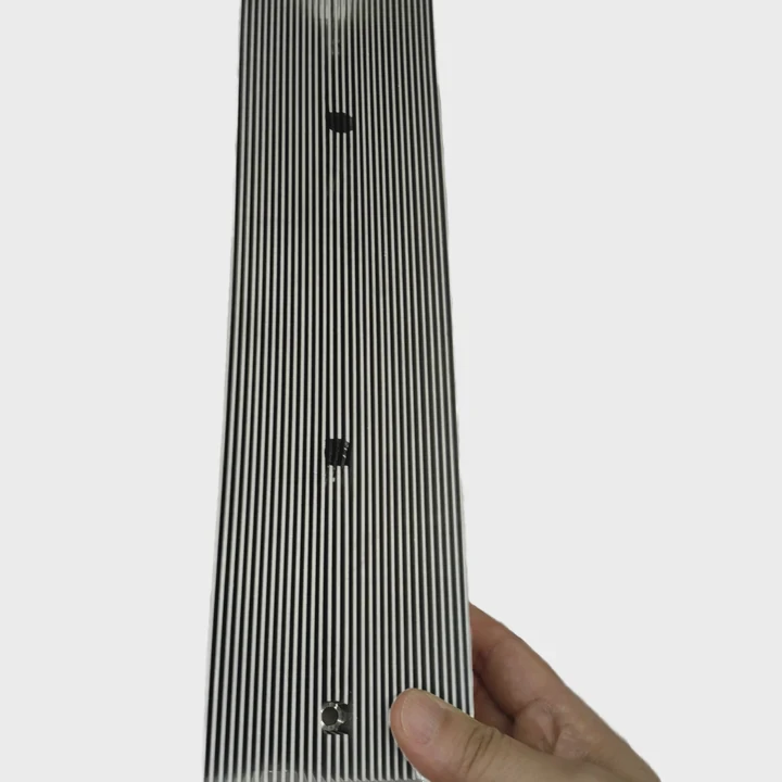
Many LED systems fail early because thermal design only focuses on peak cooling performance instead of long-term reliability.
LED lifespan improves when thermal systems provide stable junction temperature, balanced heat spreading, reliable interfaces, corrosion resistance, and consistent cooling during long operating cycles.
LED aging accelerates rapidly when temperature rises.
High Temperature Accelerates Material Degradation
Several internal materials become weaker over time under excessive heat.
These include:
- Phosphor layers
- Encapsulation materials
- Solder joints
- PCB structures
- Bond wires
Thermal cycling also creates repeated expansion and contraction stress.
Uniform Heat Distribution Prevents Hot Spots
Average temperature alone does not guarantee reliability.
Localized hot spots can damage LED packages even when system temperature appears acceptable.
Technologies That Improve Heat Spreading
| Technology | Main Function |
|---|---|
| Vapor chamber | Fast planar heat spreading |
| Heat pipes | Remote heat transfer |
| Copper base | Reduced hotspot formation |
| Graphite sheet | Thin heat distribution |
These technologies help maintain more uniform temperature across the module.
Mechanical Structure Also Affects Thermal Stability
Thermal reliability depends heavily on assembly quality.
Mounting Pressure
Uneven pressure creates air gaps and increases thermal resistance.
Surface Flatness
Poor machining quality reduces contact efficiency.
Structural Rigidity
Mechanical deformation changes thermal contact during long-term operation.
Even small assembly problems can increase junction temperature noticeably.
Environmental Protection Matters
Outdoor LED systems often face difficult environments.
Important factors include:
- High humidity
- Salt spray
- Dust exposure
- Vibration
- Rapid temperature changes
A heat sink that works indoors may fail outdoors without protective treatment.
Surface Coating Improves Long-Term Reliability
Protective coatings help maintain thermal and structural stability.
Common options include:
- Black anodizing
- Nickel plating
- Corrosion-resistant coatings
- Electrophoretic coating
These treatments reduce oxidation and environmental damage.
Thermal Expansion Matching Is Important
Different materials expand at different rates during heating.
| Material | Thermal Expansion Level |
|---|---|
| Aluminum | Higher |
| Copper | Moderate |
| Ceramic substrate | Lower |
| Silicon chip | Very low |
Large expansion mismatch creates mechanical stress during repeated heating cycles.
Reliability Testing Reveals Hidden Problems
Short thermal testing is not enough for high-reliability LED products.
Comprehensive validation usually includes:
- Thermal shock testing
- High-temperature aging
- Humidity exposure
- Vibration testing
- Continuous power cycling
These tests help identify weak points before mass production.
Complete Thermal Path Design Produces Better Results
The entire heat transfer path must work together effectively.
This path includes:
- LED chip
- Substrate
- Thermal interface material
- Heat spreader
- Heat sink
- Airflow environment
Weakness in any layer reduces overall cooling efficiency.
Many successful LED manufacturers now treat thermal management as a complete system instead of a single heat sink component.
Conclusion
LED cooling directly affects brightness, efficiency, and product lifespan. The best heat sink depends on thermal resistance targets, installation space, airflow conditions, and operating environment. Strong thermal management helps LED systems remain reliable, stable, and efficient during long-term operation.